POWER BACK DOOR SYSTEM Power Back Door cannot be Opened or Closed Using the Power Back Door Switch
DESCRIPTION
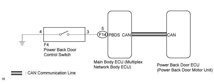
When the power back door cannot be opened or closed using the power back door control switch, one of the following may be malfunctioning: 1) power back door control switch circuit, 2) power back door ECU (power back door motor unit) or 3) main body ECU (multiplex network body ECU).
WIRING DIAGRAM
INSPECTION PROCEDURE
Note
The power back door system uses the CAN communication system. First, confirm that there is no malfunction in the CAN communication system. Refer to the How to Proceed with Troubleshooting procedure Click here.
PROCEDURE
-
READ VALUE USING INTELLIGENT TESTER (POWER BACK DOOR CONTROL SWITCH)
-
Connect the intelligent tester to the DLC3.
-
Turn the power switch on (IG).
-
Turn the intelligent tester on.
-
Enter the following menus: Body / Main Body / Data List.
-
Check the Data List to determine if the power back door control switch functions properly.
Main Body (Main Body ECU (Multiplex Network Body ECU)) Tester Display Measurement Item/Range Normal Condition Diagnostic Note Back Door Open SW Power back door control switch/ON or OFF ON: Power back door control switch pushed
OFF: Power back door control switch not pushed
- OK The power back door control switch functions as specified in the normal condition column.
NG 
INSPECT POWER BACK DOOR CONTROL SWITCH Click here
OK 
-
-
REPLACE POWER BACK DOOR ECU (POWER BACK DOOR MOTOR UNIT)
-
Replace the power back door ECU (power back door motor unit) Click here.
NEXT
-
-
INITIALIZE POWER BACK DOOR ECU (POWER BACK DOOR MOTOR UNIT)
-
Perform the initialization for the power back door ECU (power back door motor unit) Click here.
NEXT
-
-
CHECK POWER BACK DOOR OPERATION
-
Check that the power back door operates normally Click here.
OK The power back door operates normally.
NG 
REPLACE MAIN BODY ECU (MULTIPLEX NETWORK BODY ECU) Click here
OK 
END (POWER BACK DOOR ECU (POWER BACK DOOR MOTOR UNIT) WAS DEFECTIVE)
-
-
INSPECT POWER BACK DOOR CONTROL SWITCH
-
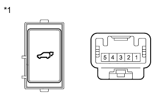
Text in Illustration *1 Component without harness connected
(Power Back Door Control Switch)
Remove the power back door control switch Click here.
-
Measure the resistance according to the value(s) in the table below.
Standard Resistance Tester Connection Switch Position Specified Condition 3 - 4 Power back door control switch not pushed (off) 10 kΩ or higher 3 - 4 Power back door control switch pushed (on) Below 1 Ω
NG
REPLACE POWER BACK DOOR CONTROL SWITCH Click here
OK
-
-
CHECK HARNESS AND CONNECTOR (POWER BACK DOOR CONTROL SWITCH - MAIN BODY ECU)
-
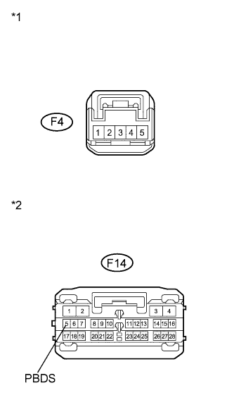
Text in Illustration *1 Front view of wire harness connector
(to Power Back Door Control Switch)
*2 Front view of wire harness connector
(to Main Body ECU (Multiplex Network Body ECU))
Disconnect the F4 power back door control switch connector and F14 main body ECU connector.
-
Measure the resistance according to the value(s) in the table below.
Standard Resistance Tester Connection Condition Specified Condition F4-3 - F14-5 (PBDS) Always Below 1 Ω F4-4 - Body ground Always Below 1 Ω F4-3 - Body ground Always 10 kΩ or higher
NG
REPAIR OR REPLACE HARNESS OR CONNECTOR
OK
REPLACE MAIN BODY ECU (MULTIPLEX NETWORK BODY ECU) Click here
-