POWER BACK DOOR SYSTEM Power Back Door cannot be Operated Using Any Switch
DESCRIPTION
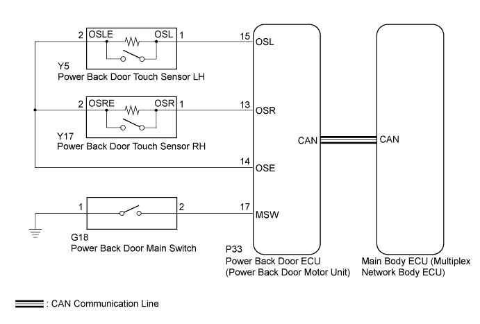
When the power back door cannot be operated using any switch, one of the following may be the cause: 1) initialization of the power back door ECU (power back door motor unit), 2) power back door touch sensor circuit, 3) power back door main switch circuit, 4) back door closer system, 5) meter/gauge system, 6) main body ECU (multiplex network body ECU) or 7) power back door ECU (power back door motor unit).
WIRING DIAGRAM
INSPECTION PROCEDURE
Note
The power back door system uses the CAN communication system. First, confirm that there is no malfunction in the CAN communication system. Refer to the How to Proceed with Troubleshooting procedure Click here.
PROCEDURE
-
INITIALIZE POWER BACK DOOR ECU (POWER BACK DOOR MOTOR UNIT)
-
Perform the initialization for the power back door ECU (power back door motor unit) Click here.
NEXT 
-
-
CHECK POWER BACK DOOR SYSTEM
-
Check power back door system operation Click here.
OK The power back door system operates normally.
NG 
CHECK BACK DOOR CLOSER SYSTEM Click here
OK 
END
-
-
CHECK BACK DOOR CLOSER SYSTEM
-
Check back door closer system operation Click here.
OK The back door closer system operates normally.
NG 
GO TO BACK DOOR CLOSER SYSTEM Click here
OK
-
-
CHECK COMBINATION METER ASSEMBLY
-
Check shift position indicator operation and that the speedometer indicates 0 km/h (0 mph) when the vehicle is stopped and the engine idling .
OK The combination meter operates normally.
NG
GO TO METER/GAUGE SYSTEM Click here
OK
-
-
CHECK POWER DOOR LOCK OPERATION (BASIC FUNCTION)
-
Check the power door lock basic function Click here.
OK The power door lock basic function operates normally.
NG
GO TO POWER DOOR LOCK CONTROL SYSTEM Click here
OK
-
-
CHECK DTC OUTPUT
-
Check for DTCs Click here.
Result Result Proceed to DTC is not output A B2222 is output B B2225 is output C B2250 is output D B2251 is output E
B
GO TO OTHER FLOW CHART (B2222) Click here
C
GO TO OTHER FLOW CHART (B2225) Click here
D
GO TO OTHER FLOW CHART (B2250) Click here
E
GO TO OTHER FLOW CHART (B2251) Click here
A
-
-
READ VALUE USING INTELLIGENT TESTER (BACK DOOR LOCK ASSEMBLY)
-
Connect the intelligent tester to the DLC3.
-
Turn the power switch on (IG).
-
Turn the intelligent tester on.
-
Enter the following menus: Body / Main Body / Data List.
-
Check the Data List to determine if the back door lock assembly functions properly.
Main Body (Main Body ECU (Multiplex Network Body ECU)) Tester Display Measurement Item/Range Normal Condition Diagnostic Note Back Door Open Back door lock/Permit or Prohibit Permit: Back door unlocked
Prohibit: Back door locked
- OK The back door functions as specified in the normal condition column.
NG
REPLACE MAIN BODY ECU (MULTIPLEX NETWORK BODY ECU) Click here
OK
-
-
READ VALUE USING INTELLIGENT TESTER (BACK DOOR LOCK ASSEMBLY)
-
Connect the intelligent tester to the DLC3.
-
Turn the power switch on (IG).
-
Turn the intelligent tester on.
-
Enter the following menus: Body / Back Door / Data List.
-
Check the Data List to determine if the back door lock assembly functions properly.
Back Door (Power Back Door ECU (Power Back Door Motor Unit)) Tester Display Measurement Item/Range Normal Condition Diagnostic Note Door Lock Status Back door lock condition signal/LOCK or UNLOCK LOCK: Back door locked
UNLOCK: Back door unlocked
- OK The back door functions as specified in the normal condition column.
NG
REPLACE POWER BACK DOOR ECU (POWER BACK DOOR MOTOR UNIT) Click here
OK
-
-
READ VALUE USING INTELLIGENT TESTER (POWER BACK DOOR TOUCH SENSOR)
-
Connect the intelligent tester to the DLC3.
-
Turn the power switch on (IG).
-
Turn the intelligent tester on.
-
Enter the following menus: Body / Back Door / Data List.
-
Check the Data List to determine if the power back door touch sensor functions properly.
Back Door (Power Back Door ECU (Power Back Door Motor Unit)) Tester Display Measurement Item/Range Normal Condition Diagnostic Note PBD Touch Sensor (Left) Power back door touch sensor LH signal/ON, OFF or Open ON: Power back door touch sensor LH pressed
OFF: Power back door touch sensor LH not pressed
Open: Power back door touch sensor LH circuit open
- PBD Touch Sensor (Right) Power back door touch sensor RH signal/ON, OFF or Open ON: Power back door touch sensor RH pressed
OFF: Power back door touch sensor RH not pressed
Open: Power back door touch sensor RH circuit open
- Result Result Proceed to On the intelligent tester screen, ON or OFF is displayed accordingly. A On the intelligent tester screen, ON or OFF is not displayed accordingly or Open is displayed. B
B
GO TO OTHER FLOW CHART (TOUCH SENSOR CIRCUIT) Click here
A
-
-
READ VALUE USING INTELLIGENT TESTER (POWER BACK DOOR MAIN SWITCH)
-
Connect the intelligent tester to the DLC3.
-
Turn the power switch on (IG).
-
Turn the intelligent tester on.
-
Enter the following menus: Body / Back Door / Data List.
-
Check the Data List to determine if the power back door main switch functions properly.
Back Door (Power Back Door ECU (Power Back Door Motor Unit)) Tester Display Measurement Item/Range Normal Condition Diagnostic Note PBD Main SW Power back door main switch/ON or OFF ON: Power back door main switch not pushed
OFF: Power back door main switch pushed
- OK The power back door main switch functions as specified in the normal condition column.
NG
INSPECT POWER BACK DOOR MAIN SWITCH Click here
OK
REPLACE POWER BACK DOOR ECU (POWER BACK DOOR MOTOR UNIT) Click here
-
-
INSPECT POWER BACK DOOR MAIN SWITCH
-
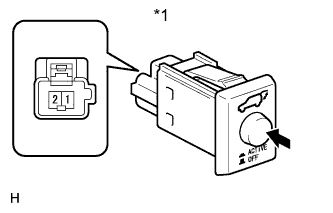
Text in Illustration *1 Component without harness connected
(Power Back Door Main Switch)
Remove the power back door main switch Click here.
-
Measure the resistance according to the value(s) in the table below.
Standard Resistance Tester Connection Switch Condition Specified Condition 1 - 2 Power back door main switch pushed Below 1 Ω 1 - 2 Power back door main switch not pushed 10 kΩ or higher
NG
REPLACE POWER BACK DOOR MAIN SWITCH Click here
OK
-
-
CHECK HARNESS AND CONNECTOR (POWER BACK DOOR MAIN SWITCH - POWER BACK DOOR ECU)
-
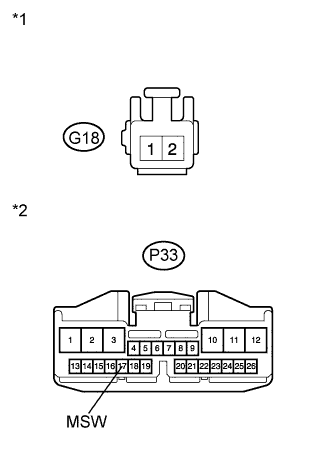
Text in Illustration *1 Front view of wire harness connector
(to Power Back Door Main Switch)
*2 Front view of wire harness connector
(to Power Back Door ECU (Power Back Door Motor Unit))
Disconnect the G18 power back door main switch connector and P33 power back door ECU connector.
-
Measure the resistance according to the value(s) in the table below.
Standard Resistance Tester Connection Condition Specified Condition G18-2 - P33-17 (MSW) Always Below 1 Ω G18-1 - Body ground Always Below 1 Ω G18-2 - Body ground Always 10 kΩ or higher
NG
REPAIR OR REPLACE HARNESS OR CONNECTOR
OK
REPLACE POWER BACK DOOR ECU (POWER BACK DOOR MOTOR UNIT) Click here
-
-
REPLACE POWER BACK DOOR ECU (POWER BACK DOOR MOTOR UNIT)
-
Replace the power back door ECU (power back door motor unit) Click here.
NEXT
-
-
CHECK POWER BACK DOOR SYSTEM
-
Check the power back door system Click here.
OK The power back door system operates normally.
NG
REPLACE MAIN BODY ECU (MULTIPLEX NETWORK BODY ECU) Click here
OK
END (POWER BACK DOOR ECU WAS DEFECTIVE)
-