POWER BACK DOOR SYSTEM TERMINALS OF ECU

-
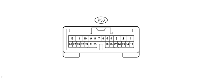
CHECK POWER BACK DOOR ECU (POWER BACK DOOR MOTOR UNIT)
-
Disconnect the P33 ECU connector.
-
Measure the voltage and resistance according to the value(s) in the table below.
Tech Tips
Measure the values on the wire harness side with the connector disconnected.
Tester Connection Wiring Color Terminal Description Condition Specified Condition P33-10 (ECUB) - Body ground BR - Body ground Auxiliary battery power supply Power switch off 11 to 14 V P33-12 (B) - Body ground Y - Body ground Auxiliary battery power supply Power switch off 11 to 14 V P33-8 (IG) - Body ground SB - Body ground IG power supply Power switch on (IG) 11 to 14 V P33-8 (IG) - Body ground SB - Body ground IG power supply Power switch off Below 1 V P33-17 (MSW) - Body ground BR - Body ground Power back door main switch signal Power back door main switch not pushed Below 1 Ω P33-17 (MSW) - Body ground BR - Body ground Power back door main switch signal Power back door main switch pushed 10 kΩ or higher P33-4 (DS1) - Body ground GR - Body ground Power back door closer switch signal Power back door closer switch on Below 1 Ω P33-4 (DS1) - Body ground GR - Body ground Power back door closer switch signal Power back door closer switch off 10 kΩ or higher P33-15 (OSL) - P33-14 (OSE) G - Y Power back door touch sensor LH signal Power back door touch sensor LH not pressed 950 to 1050 Ω P33-15 (OSL) - P33-14 (OSE) G - Y Power back door touch sensor LH signal Back door touch sensor LH pressed Below 100 Ω P33-13 (OSR) - P33-14 (OSE) L - Y Power back door touch sensor RH signal Back door touch sensor RH not pressed 950 to 1050 Ω P33-13 (OSR) - P33-14 (OSE) L - Y Power back door touch sensor RH signal Power back door touch sensor RH pressed Below 100 Ω P33-11 (GND) - Body ground W-B - Body ground Ground Always Below 1 Ω If the result is not as specified, there may be a malfunction in the wire harness.
-
Reconnect the P33 ECU connector.
-
Initialize the power back door system Click here.
-
Measure the voltage according to the value(s) in the table below.
Tester Connection Wiring Color Terminal Description Condition Specified Condition P33-17 (MSW) - Body ground BR - Body ground Power back door main switch signal Power back door main switch not pushed Below 1 V P33-17 (MSW) - Body ground BR - Body ground Power back door main switch signal Power back door main switch pushed Pulse generation P33-26 (BZR+) - Body ground W - Body ground Power back door warning buzzer signal input Back door warning buzzer sounding Pulse generation P33-26 (BZR+) - Body ground W - Body ground Power back door warning buzzer signal input Back door warning buzzer stopped Below 1 V P33-2 (DC+) - P33-1 (DC-) LG - W-B Power back door lock motor signal Back door lock motor operating 11 to 14 V P33-2 (DC+) - P33-1 (DC-) LG - W-B Power back door lock motor signal Back door lock motor stopped Below 1 V P33-4 (DS1) - Body ground GR - Body ground Power back door closer switch signal Power back door closer switch on Below 1 V P33-4 (DS1) - Body ground GR - Body ground Power back door closer switch signal Power back door closer switch off Pulse generation P33-15 (OSL) - P33-14 (OSE) G - Y Power back door touch sensor LH signal Power back door touch sensor LH not pressed 4 to 6 V P33-15 (OSL) - P33-14 (OSE) G - Y Power back door touch sensor LH signal Back door touch sensor LH pressed Below 1 V P33-13 (OSR) - P33-14 (OSE) L - Y Power back door touch sensor RH signal Back door touch sensor RH not pressed 4 to 6 V P33-13 (OSR) - P33-14 (OSE) L - Y Power back door touch sensor RH signal Power back door touch sensor RH pressed Below 1 V If the result is not as specified, the ECU may have a malfunction.
-
-
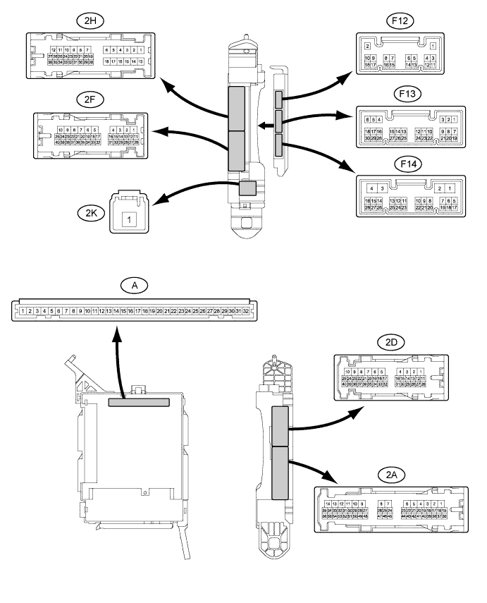
CHECK MAIN BODY ECU (MULTIPLEX NETWORK BODY ECU)
-
Disconnect the F14 connector.
-
Measure the resistance according to the value(s) in the table below.
Tech Tips
Measure the values on the wire harness side with the connector disconnected.
Tester Connection Wiring Color Terminal Description Condition Specified Condition F14-5 (PBDS) - Body ground V - Body ground Power back door open/close switch signal circuit Power back door open/close switch on Below 1 Ω F14-5 (PBDS) - Body ground V - Body ground Power back door open/close switch signal circuit Power back door open/close switch off 10 kΩ or higher If the result is not as specified, there may be a malfunction in the wire harness.
-
Reconnect the F14 connector.
-
Measure the voltage according to the value(s) in the table below.
Tester Connection Wiring Color Terminal Description Condition Specified Condition F14-5 (PBDS) - Body ground V - Body ground Power back door control switch signal Power back door control switch on Below 1 V F14-5 (PBDS) - Body ground V - Body ground Power back door control switch signal Power back door control switch off Pulse generation If the result is not as specified, the power back door ECU (power back door motor unit) may have a malfunction.
-
-
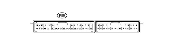
CHECK CERTIFICATION ECU (SMART KEY ECU ASSEMBLY)
-
Disconnect the F58 connector.
-
Measure the resistance according to the value(s) in the table below.
Tech Tips
Measure the values on the wire harness side with the connector disconnected.
Tester Connection Wiring Color Terminal Description Condition Specified Condition F58-22 (TSW5) - Body ground L - Body ground Back door opener switch signal circuit Back door opener switch on Below 1 Ω F58-22 (TSW5) - Body ground L - Body ground Back door opener switch signal circuit Back door opener switch off 10 kΩ or higher If the result is not as specified, there may be a malfunction on the wire harness side.
-
Reconnect the F58 connector.
-
Measure the voltage according to the value(s) in the table below.
Tester Connection Wiring Color Terminal Description Condition Specified Condition F58-22 (TSW5) - Body ground L - Body ground Back door opener switch signal circuit Back door opener switch off Pulse generation F58-22 (TSW5) - Body ground L - Body ground Back door opener switch signal circuit Back door opener switch on Below 1 V If the result is not as specified, the ECU may have a malfunction.
-