BACK DOOR CLOSER SYSTEM Back Door cannot be Opened
DESCRIPTION
When the back door cannot be opened, one of the following may be malfunctioning: 1) power back door ECU (power back door motor unit) 2) back door lock assembly, 3) back door opener switch assembly, 4) main body ECU (multiplex network body ECU) or 5) certification ECU (smart key ECU assembly).
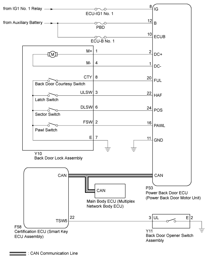
WIRING DIAGRAM
INSPECTION PROCEDURE
Note
The back door closer system uses the CAN communication system. First, confirm that there is no malfunction in the CAN communication system. Refer to the How to Proceed with Troubleshooting procedure Click here.
PROCEDURE
-
CHECK POWER DOOR LOCK OPERATION (BASIC FUNCTION)
-
Check the power door lock basic function Click here.
OK The power door lock basic function can be operated normally.
NG 
GO TO POWER DOOR LOCK CONTROL SYSTEM Click here
OK 
-
-
READ VALUE USING INTELLIGENT TESTER
-
Connect the intelligent tester to the DLC3.
-
Turn the power switch on (IG).
-
Turn the intelligent tester on.
-
Enter the following menus: Body / Main Body / Data List.
-
Check if the back door lock functions properly.
Main Body (Main Body ECU (Multiplex Network Body ECU)) Tester Display Measurement Item/Range Normal Condition Diagnostic Note Back Door Open Back door lock/Permit or Prohibit Permit: Back door unlocked
Prohibit: Back door locked
- OK The back door functions as specified in the normal condition column.
NG
REPLACE MAIN BODY ECU (MULTIPLEX NETWORK BODY ECU) Click here
OK
-
-
READ VALUE USING INTELLIGENT TESTER
-
Connect the intelligent tester to the DLC3.
-
Turn the power switch on (IG).
-
Turn the intelligent tester on.
-
Enter the following menus: Body / Back Door / Data List.
-
Check if the back door lock functions properly.
Back Door (Power Back Door ECU (Power Back Door Motor Unit)) Tester Display Measurement Item/Range Normal Condition Diagnostic Note Door Lock Status Back door lock condition signal/Lock or Unlock Lock: Back door locked
Unlock: Back door unlocked
- OK The back door functions as specified in the normal condition column.
NG 
REPLACE POWER BACK DOOR ECU (POWER BACK DOOR MOTOR UNIT) Click here
OK
-
-
READ VALUE USING INTELLIGENT TESTER
-
Connect the intelligent tester to the DLC3.
-
Turn the power switch on (IG).
-
Turn the intelligent tester on.
-
Enter the following menus: Body / Entry&Start / Data List.
-
Check if the switch functions properly.
Entry&Start (Certification ECU (Smart Key ECU Assembly)) Tester Display Measurement Item/Range Normal Condition Diagnostic Note Tr/B-Door Unlock SW Back door opener switch/ON or OFF ON: Back door opener switch pushed
OFF: Back door opener switch not pushed
- OK The back door opener switch functions as specified in the normal condition column.
NG
INSPECT BACK DOOR OPENER SWITCH ASSEMBLY Click here
OK
-
-
INSPECT BACK DOOR LOCK ASSEMBLY
-
Remove the back door lock assembly Click here.
-
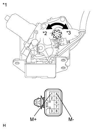
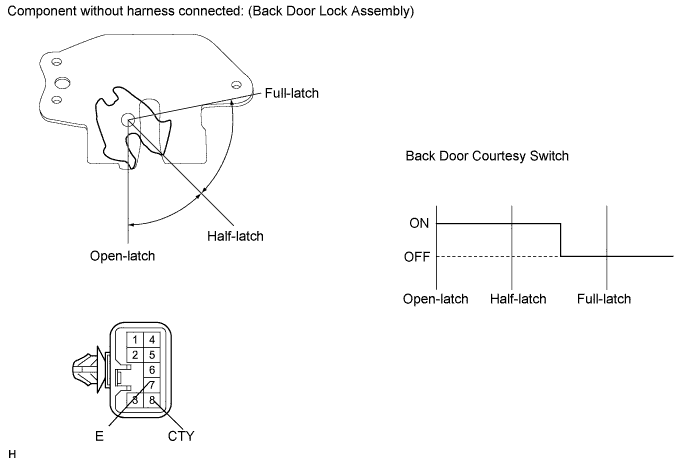
Text in Illustration *1 Component without harness connected
(Back Door Lock Assembly)
*2 Counterclockwise *3 Clockwise Check the operation of the back door closer motor.
-
Apply auxiliary battery voltage and check the operation of the door lock motor.
OK Tester Connection Specified Condition Auxiliary battery positive (+) → 1 (M+)
Auxiliary battery negative (-) → 4 (M-)
Latch turns to full-latch position (clockwise rotation) Auxiliary battery positive (+) → 4 (M-)
Auxiliary battery negative (-) → 1 (M+)
Latch turns to open-latch position (counterclockwise rotation)
-
-
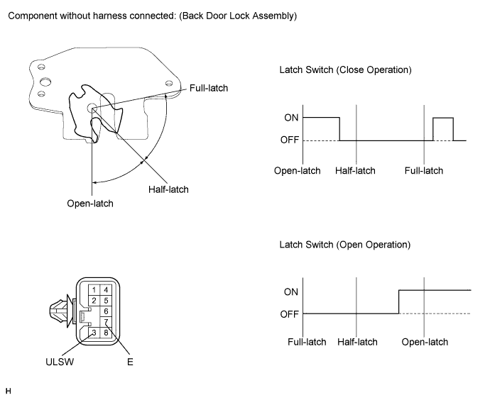
Check operation of the latch switch.
-
Measure the resistance according to the value(s) in the table below.
Standard Resistance Close Operation Tester Connection Condition Specified Condition 3 (ULSW) - 7 (E) Open-latch Below 1 Ω 3 (ULSW) - 7 (E) Open-latch → Half-latch Below 1 Ω → 10 kΩ or higher 3 (ULSW) - 7 (E) Half-latch 10 kΩ or higher 3 (ULSW) - 7 (E) Full-latch 10 kΩ or higher 3 (ULSW) - 7 (E) Over stroke 10 kΩ or higher → Below 1 Ω → 10 kΩ or higher Open Operation Tester Connection Condition Specified Condition 3 (ULSW) - 7 (E) Full-latch 10 kΩ or higher 3 (ULSW) - 7 (E) Half-latch 10 kΩ or higher 3 (ULSW) - 7 (E) Half-latch → Open-latch 10 kΩ or higher → Below 1 Ω 3 (ULSW) - 7 (E) Open-latch Below 1 Ω
-
-
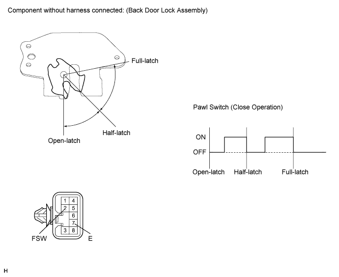
Check the operation of the pawl switch.
-
Measure the resistance according to the value(s) in the table below.
Standard Resistance Close Operation Tester Connection Condition Specified Condition 2 (FSW) - 7 (E) Open-latch 10 kΩ or higher 2 (FSW) - 7 (E) Open-latch → Half-latch 10 kΩ or higher → Below 1 Ω → 10 kΩ or higher 2 (FSW) - 7 (E) Half-latch 10 kΩ or higher 2 (FSW) - 7 (E) Half-latch → Full-latch 10 kΩ or higher → Below 1 Ω → 10 kΩ or higher 2 (FSW) - 7 (E) Full-latch 10 kΩ or higher
-
-
Check the operation of the back door courtesy switch.
-
Measure the resistance according to the value(s) in the table below.
Standard Resistance Tester Connection Condition Specified Condition 8 (CTY) - 7 (E) Open-latch Below 1 Ω 8 (CTY) - 7 (E) Half-latch Below 1 Ω 8 (CTY) - 7 (E) Full-latch 10 kΩ or higher
-
-
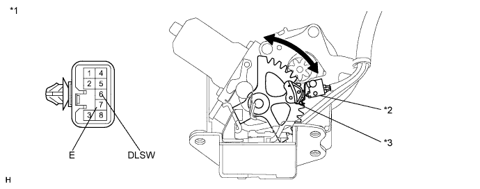
Check the operation of the sector switch.
-
Measure the resistance according to the value(s) in the table below.
Standard Resistance Tester Connection Condition Specified Condition 6 (DLSW) - 7 (E) Sector gear in neutral position (sector switch on) Below 1 Ω 6 (DLSW) - 7 (E) Sector gear not in neutral position (sector switch off) 10 kΩ or higher Text in Illustration *1 Component without harness connected
(Back Door Lock Assembly)
*2 Sector Switch *3 Sector Gear - -
-
NG
REPLACE BACK DOOR LOCK ASSEMBLY Click here
OK
-
-
CHECK HARNESS AND CONNECTOR (BACK DOOR LOCK ASSEMBLY - POWER BACK DOOR ECU)
-
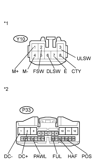
Text in Illustration *1 Front view of wire harness connector
(to Back Door Lock Assembly)
*2 Front view of wire harness connector
(to Power Back Door ECU (Power Back Door Motor Unit))
Disconnect the Y10 back door lock connector and P33 ECU connector.
-
Measure the resistance according to the value(s) in the table below.
Standard Resistance Tester Connection Condition Specified Condition Y10-1 (M+) - P33-2 (DC+) Always Below 1 Ω Y10-4 (M-) - P33-1 (DC-) Always Below 1 Ω Y10-3 (ULSW) - P33-22 (HAF) Always Below 1 Ω Y10-6 (DLSW) - P33-24 (POS) Always Below 1 Ω Y10-8 (CTY) - P33-20 (FUL) Always Below 1 Ω Y10-2 (FSW) - P33-16 (PAWL) Always Below 1 Ω Y10-7 (E) - Body ground Always Below 1 Ω Y10-1 (M+) - Body ground Always 10 kΩ or higher Y10-4 (M-) - Body ground Always 10 kΩ or higher Y10-3 (ULSW) - Body ground Always 10 kΩ or higher Y10-6 (DLSW) - Body ground Always 10 kΩ or higher Y10-8 (CTY) - Body ground Always 10 kΩ or higher Y10-2 (FSW) - Body ground Always 10 kΩ or higher
NG
REPAIR OR REPLACE HARNESS OR CONNECTOR
OK
-
-
REPLACE POWER BACK DOOR ECU (POWER BACK DOOR MOTOR UNIT)
-
Replace the power back door ECU (power back door motor unit) Click here.
NEXT
-
-
CHECK BACK DOOR OPEN FUNCTION
-
Check that the back door can be opened.
OK The back door can be opened normally.
NG
REPLACE CERTIFICATION ECU (SMART KEY ECU ASSEMBLY)
OK 
END (POWER BACK DOOR ECU WAS DEFECTIVE)
-
-
INSPECT BACK DOOR OPENER SWITCH ASSEMBLY
-
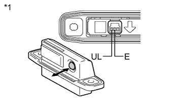
Text in Illustration *1 Component without harness connected
(Back Door Opener Switch Assembly)
Remove the back door opener switch assembly Click here.
-
Measure the resistance according to the value(s) in the table below.
Standard Resistance Tester Connection Condition Specified Condition 2 (E) - 3 (UL) Back door opener switch not pushed 10 kΩ or higher 2 (E) - 3 (UL) Back door opener switch pushed Below 1 Ω
NG
REPLACE BACK DOOR OPENER SWITCH ASSEMBLY Click here
OK
-
-
CHECK HARNESS AND CONNECTOR (BACK DOOR OPENER SWITCH ASSEMBLY - CERTIFICATION ECU)
-
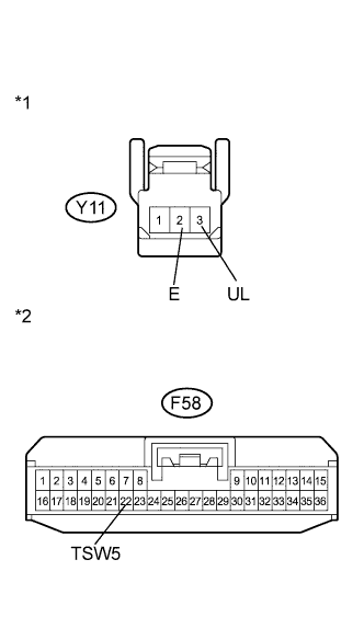
Text in Illustration *1 Front view of wire harness connector
(to Back Door Opener Switch Assembly)
*2 Front view of wire harness connector
(to Certification ECU (Smart Key ECU Assembly))
Disconnect the Y11 switch connector and F58 ECU connector.
-
Measure the resistance according to the value(s) in the table below.
Standard Resistance Tester Connection Condition Specified Condition Y11-3 (UL) - F58-22 (TSW5) Always Below 1 Ω Y11-2 (E) - Body ground Always Below 1 Ω Y11-3 (UL) - Body ground Always 10 kΩ or higher
NG
REPAIR OR REPLACE HARNESS OR CONNECTOR
OK
REPLACE CERTIFICATION ECU (SMART KEY ECU ASSEMBLY)
-
-
REPLACE POWER BACK DOOR ECU (POWER BACK DOOR MOTOR UNIT)
-
Replace the power back door ECU (power back door motor unit) Click here.
NEXT
-
-
CHECK BACK DOOR OPEN FUNCTION
-
Check that the back door can be opened.
OK The back door can be opened normally.
NG
REPLACE MAIN BODY ECU (MULTIPLEX NETWORK BODY ECU) Click here
OK
END (POWER BACK DOOR ECU WAS DEFECTIVE)
-