BACK DOOR CLOSER SYSTEM Back Door Closer does not Operate
DESCRIPTION
When the back door closer does not operate, one of the following may be the cause 1) improper fit of the back door, or a foreign object is stuck in the back door 2) initialization of the power back door ECU (power back door motor unit), 3) a malfunction in the power back door ECU (power back door motor unit) power source circuit, 4) a malfunction in the back door lock circuit or 5) a malfunction in the power back door ECU (power back door motor unit).
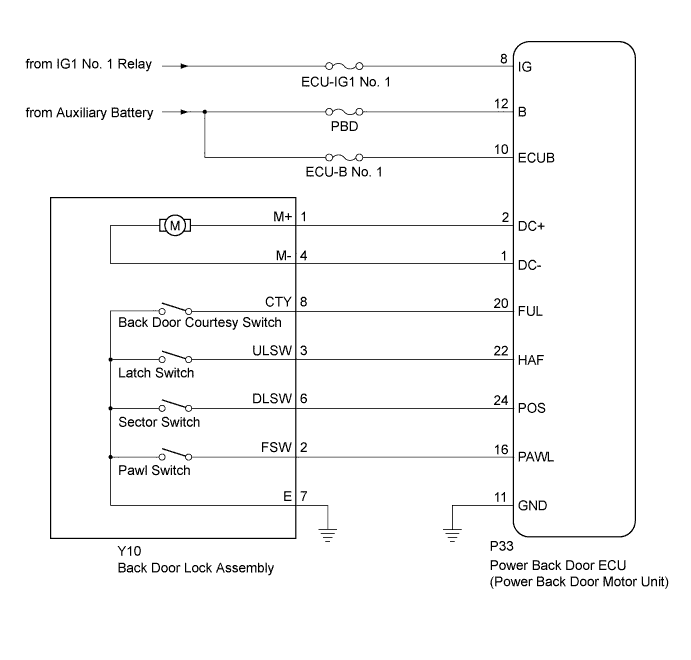
WIRING DIAGRAM
INSPECTION PROCEDURE
Note
Inspect fuses for circuits related to this system before performing the following inspection procedure.
PROCEDURE
-
CHECK BACK DOOR LOCK FUNCTION
-
Check if the back door can be fully closed by hand.
OK The back door can be closed normally.
NG 
IMPROPER FIT OF BACK DOOR, OR A FOREIGN OBJECT IS STUCK IN BACK DOOR
OK 
-
-
INITIALIZE POWER BACK DOOR ECU (POWER BACK DOOR MOTOR UNIT)
-
Perform the initialization of the power back door ECU (power back door motor unit) Click here.
NEXT
-
-
CHECK BACK DOOR CLOSER SYSTEM
-
Check back door closer system operation Click here.
OK The back door closer system operates normally.
NG 
READ VALUE USING INTELLIGENT TESTER (POWER BACK DOOR TOUCH SENSOR) Click here
OK 
END
-
-
READ VALUE USING INTELLIGENT TESTER (POWER BACK DOOR TOUCH SENSOR)
-
Connect the intelligent tester to the DLC3.
-
Turn the power switch on (IG).
-
Turn the intelligent tester on.
-
Enter the following menus: Body / Back Door / Data List.
-
Check the Data List to determine if the power back door touch sensor functions properly.
Back Door (Power Back Door ECU (Power Back Door Motor Unit)) Tester Display Measurement Item/Range Normal Condition Diagnostic Note PBD Touch Sensor (Right) Power back door touch sensor RH signal/ON, OFF or Open ON: Power back door touch sensor RH pressed
OFF: Power back door touch sensor RH not pressed
Open: Power back door touch sensor RH circuit open
- PBD Touch Sensor (Left) Power back door touch sensor LH signal/ON, OFF or Open ON: Power back door touch sensor LH pressed
OFF: Power back door touch sensor LH not pressed
Open: Power back door touch sensor LH circuit open
- Result Result Proceed to On the intelligent tester screen, ON or OFF is displayed accordingly. A On the intelligent tester screen, ON or OFF is not displayed accordingly or Open is displayed. B
B
GO TO OTHER FLOW CHART (TOUCH SENSOR CIRCUIT) Click here
A
-
-
CHECK DTC OUTPUT
-
Clear the DTCs Click here.
-
Recheck for DTCs.
Result Result Proceed to DTC is not output A B2250 is output B B2251 is output C
B
GO TO DTC CHART (B2250) Click here
C
GO TO DTC CHART (B2251) Click here
A
-
-
CHECK HARNESS AND CONNECTOR (POWER SOURCE)
-
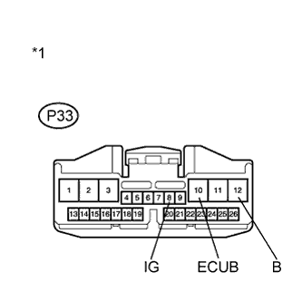
Text in Illustration *1 Front view of wire harness connector
(to Power Back Door ECU (Power Back Door Motor Unit))
Disconnect the P33 power back door ECU connector.
-
Measure the voltage according to the value(s) in the table below.
Standard Voltage Tester Connection Condition Specified Condition P33-8 (IG) - Body ground Power switch on (IG) 11 to 14 V P33-10 (ECUB) - Body ground Power switch off 11 to 14 V P33-12 (B) - Body ground Power switch off 11 to 14 V
NG
REPAIR OR REPLACE HARNESS OR CONNECTOR
OK
-
-
CHECK HARNESS AND CONNECTOR (BODY GROUND)
-
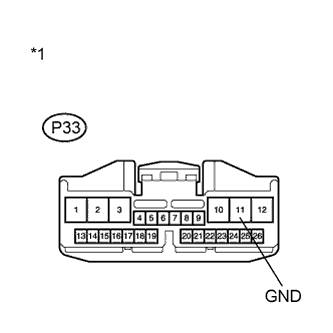
Text in Illustration *1 Front view of wire harness connector
(to Power Back Door ECU (Power Back Door Motor Unit))
Disconnect the P33 power back door ECU connector.
-
Measure the resistance according to the value(s) in the table below.
Standard Resistance Tester Connection Condition Specified Condition P33-11 (GND) - Body ground Always Below 1 Ω
NG
REPAIR OR REPLACE HARNESS OR CONNECTOR
OK
-
-
INSPECT BACK DOOR LOCK ASSEMBLY
-
Remove the back door lock assembly Click here.
-
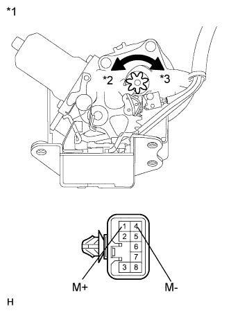
Text in Illustration *1 Component without harness connected
(Back Door Lock Assembly)
*2 Counterclockwise *3 Clockwise Check the operation of the back door closer motor.
-
Apply auxiliary battery voltage and check the operation of the door lock motor.
OK Tester Connection Specified Condition Auxiliary battery positive (+) → 1 (M+)
Auxiliary battery negative (-) → 4 (M-)
Latch turns to full-latch position (clockwise rotation) Auxiliary battery positive (+) → 4 (M-)
Auxiliary battery negative (-) → 1 (M+)
Latch turns to open-latch position (counterclockwise rotation)
-
-
Check the operation of the latch switch.
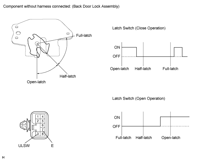
-
Measure the resistance according to the value(s) in the table below.
Standard Resistance Close Operation Tester Connection Condition Specified Condition 3 (ULSW) - 7 (E) Open-latch Below 1 Ω 3 (ULSW) - 7 (E) Open-latch → Half-latch Below 1 Ω → 10 kΩ or higher 3 (ULSW) - 7 (E) Half-latch 10 kΩ or higher 3 (ULSW) - 7 (E) Full-latch 10 kΩ or higher 3 (ULSW) - 7 (E) Over stroke 10 kΩ or higher → Below 1 Ω → 10 kΩ or higher Open Operation Tester Connection Condition Specified Condition 3 (ULSW) - 7 (E) Full-latch 10 kΩ or higher 3 (ULSW) - 7 (E) Half-latch 10 kΩ or higher 3 (ULSW) - 7 (E) Half-latch → Open-latch 10 kΩ or higher → Below 1 Ω 3 (ULSW) - 7 (E) Open-latch Below 1 Ω
-
-
Check the operation of the pawl switch.
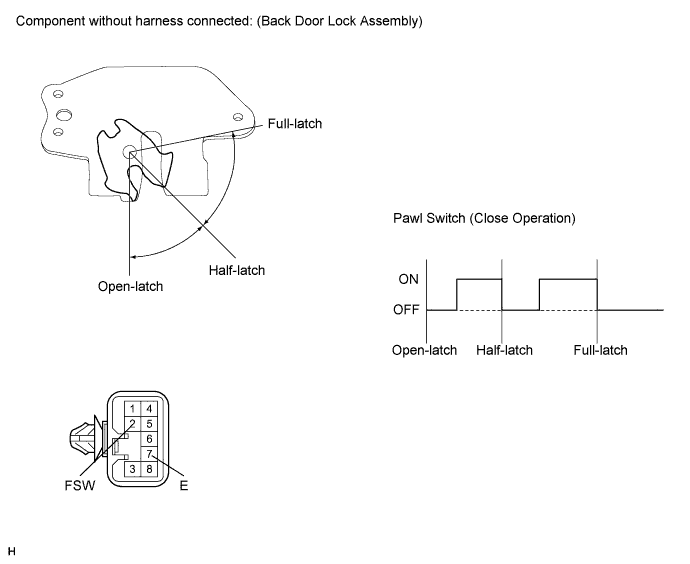
-
Measure the resistance according to the value(s) in the table below.
Standard Resistance Close Operation Tester Connection Condition Specified Condition 2 (FSW) - 7 (E) Open-latch 10 kΩ or higher 2 (FSW) - 7 (E) Open-latch → Half-latch 10 kΩ or higher → Below 1 Ω → 10 kΩ or higher 2 (FSW) - 7 (E) Half-latch 10 kΩ or higher 2 (FSW) - 7 (E) Half-latch → Full-latch 10 kΩ or higher → Below 1 Ω → 10 kΩ or higher 2 (FSW) - 7 (E) Full-latch 10 kΩ or higher
-
-
Check the operation of the back door courtesy switch.
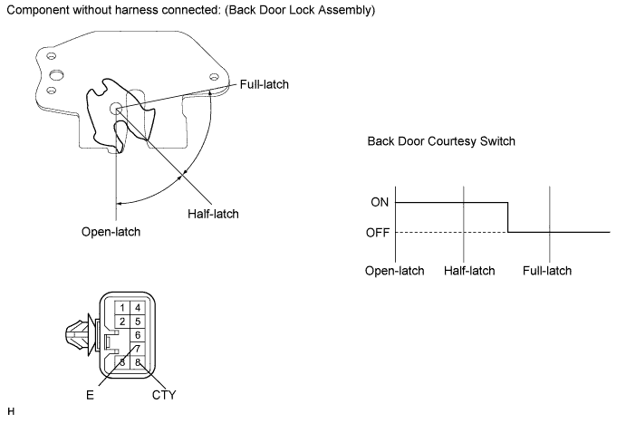
-
Measure the resistance according to the value(s) in the table below.
Standard Resistance Tester Connection Condition Specified Condition 8 (CTY) - 7 (E) Open-latch Below 1 Ω 8 (CTY) - 7 (E) Half-latch Below 1 Ω 8 (CTY) - 7 (E) Full-latch 10 kΩ or higher
-
-
Check the operation of the sector switch.
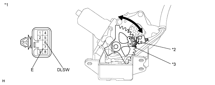
-
Measure the resistance according to the value(s) in the table below.
Standard Resistance Tester Connection Condition Specified Condition 6 (DLSW) - 7 (E) Sector gear in neutral position (sector switch on) Below 1 Ω 6 (DLSW) - 7 (E) Sector gear not in neutral position (sector switch off) 10 kΩ or higher Text in Illustration *1 Component without harness connected
(Back Door Lock Assembly)
*2 Sector Switch *3 Sector Gear - -
-
NG
REPLACE BACK DOOR LOCK ASSEMBLY Click here
OK
-
-
CHECK HARNESS AND CONNECTOR (BACK DOOR LOCK - POWER BACK DOOR ECU)
-
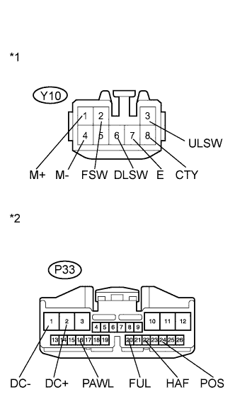
Text in Illustration *1 Front view of wire harness connector
(to Back Door Lock Assembly)
*2 Front view of wire harness connector
(to Power Back Door ECU (Power Back Door Motor Unit))
Disconnect the Y10 back door lock connector and P33 ECU connector.
-
Measure the resistance according to the value(s) in the table below.
Standard Resistance Tester Connection Condition Specified Condition Y10-1 (M+) - P33-2 (DC+) Always Below 1 Ω Y10-4 (M-) - P33-1 (DC-) Always Below 1 Ω Y10-3 (ULSW) - P33-22 (HAF) Always Below 1 Ω Y10-6 (DLSW) - P33-24 (POS) Always Below 1 Ω Y10-8 (CTY) - P33-20 (FUL) Always Below 1 Ω Y10-7 (E) - Body ground Always Below 1 Ω Y10-1 (M+) - Body ground Always 10 kΩ or higher Y10-4 (M-) - Body ground Always 10 kΩ or higher Y10-3 (ULSW) - Body ground Always 10 kΩ or higher Y10-6 (DLSW) - Body ground Always 10 kΩ or higher Y10-8 (CTY) - Body ground Always 10 kΩ or higher
NG
REPAIR OR REPLACE HARNESS OR CONNECTOR
OK
REPLACE POWER BACK DOOR ECU (POWER BACK DOOR MOTOR UNIT) Click here
-