POWER BACK DOOR SYSTEM Power Back Door cannot be Closed Using the Power Back Door Closer Switch
DESCRIPTION
When the power back door cannot be closed using the power back door closer switch, either of the following may be malfunctioning: 1) power back door closer switch circuit or 2) power back door ECU (power back door motor unit).
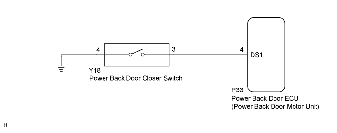
WIRING DIAGRAM
INSPECTION PROCEDURE
PROCEDURE
-
READ VALUE USING INTELLIGENT TESTER (POWER BACK DOOR CLOSER SWITCH)
-
Connect the intelligent tester to the DLC3.
-
Turn the power switch on (IG).
-
Turn the intelligent tester on.
-
Enter the following menus: Body / Back Door / Data List.
-
Check the Data List to determine if the power back door closer switch functions properly.
Back Door (Power Back Door ECU (Power Back Door Motor Unit)) Tester Display Measurement Item/Range Normal Condition Diagnostic Note PBD Close SW Power back door closer switch signal/ON or OFF ON: Power back door closer switch on
OFF: Power back door closer switch off
- OK The power back door closer switch functions as specified in the normal condition column.
NG 
INSPECT POWER BACK DOOR CLOSER SWITCH Click here
OK 
REPLACE POWER BACK DOOR ECU (POWER BACK DOOR MOTOR UNIT) Click here
-
-
INSPECT POWER BACK DOOR CLOSER SWITCH
-
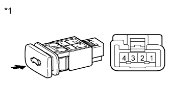
Text in Illustration *1 Component without harness connected
(Power Back Door Closer Switch)
Remove the power back door closer switch Click here.
-
Measure the resistance according to the value(s) in the table below.
Standard Resistance Tester Connection Switch Condition Specified Condition 3 - 4 Pushed (on) Below 1 Ω 3 - 4 Free (off) 10 kΩ or higher
NG 
REPLACE POWER BACK DOOR CLOSER SWITCH Click here
OK 
-
-
CHECK HARNESS AND CONNECTOR (POWER BACK DOOR CLOSER SWITCH - POWER BACK DOOR ECU)
-
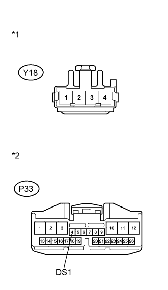
Text in Illustration *1 Front view of wire harness connector
(to Power Back Door Closer Switch)
*2 Front view of wire harness connector
(to Power Back Door ECU)
Disconnect the Y18 power back door closer switch connector and P33 power back door ECU connector.
-
Measure the resistance according to the value(s) in the table below.
Standard Resistance Tester Connection Condition Specified Condition Y18-3 - P33-4 (DS1) Always Below 1 Ω Y18-4 - Body ground Always Below 1 Ω Y18-3 - Body ground Always 10 kΩ or higher
NG
REPAIR OR REPLACE HARNESS OR CONNECTOR
OK
REPLACE POWER BACK DOOR ECU (POWER BACK DOOR MOTOR UNIT) Click here
-