ELECTRONICALLY CONTROLLED BRAKE SYSTEM, Diagnostic DTC:C1319/35

| DTC Code | DTC Name |
|---|---|
| C1319/35 | SCSS Changeover Solenoid Malfunction |
DESCRIPTION
The stroke simulator solenoid generates pedal reactive effort during electronically controlled brake system control. If one of the four wheels loses brake accumulator function, the simulator operation is prohibited.
| DTC Code | INF Code | DTC Detection Condition | Trouble Area |
|---|---|---|---|
| C1319/35 | 71 | Either of the following is detected:
|
|
| ↑ | 72 | Current leaks for 0.05 seconds or more when SS is off. | ↑ |
| ↑ | 73 | Open circuit in SS continues for 0.05 seconds or more. | ↑ |
| ↑ | 74 | Overcurrent in SS continues for 0.05 seconds or more. | ↑ |
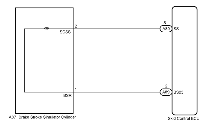
WIRING DIAGRAM
INSPECTION PROCEDURE
Note
When replacing the skid control ECU, perform initialization and calibration of the linear solenoid valve Click here.
PROCEDURE
-
INSPECT BRAKE STROKE SIMULATOR CYLINDER
-
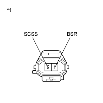
Text in Illustration *1 Component without harness connected
(Brake Stroke Simulator Cylinder)
Make sure that there is no looseness at the locking part and the connecting part of the connector.
-
Disconnect the brake stroke simulator cylinder connector.
-
Measure the resistance according to the value(s) in the table below.
Standard Resistance Tester Connection Condition Specified Condition 1 (BSR) - 2 (SCSS) Always 21.45 to 23.15 Ω 1 (BSR) - Body ground Always 10 kΩ or higher Result Result Proceed to OK A NG (for LHD) B NG (for RHD) C
B 
REPLACE BRAKE STROKE SIMULATOR CYLINDER Click here
C
REPLACE BRAKE STROKE SIMULATOR CYLINDER Click here
A 
-
-
CHECK HARNESS AND CONNECTOR (SKID CONTROL ECU - BRAKE STROKE SIMULATOR CYLINDER)
-
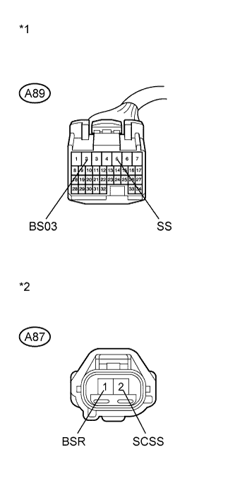
Text in Illustration *1 Front view of wire harness connector
(to Skid Control ECU)
*2 Front view of wire harness connector
(to Brake Stroke Simulator Cylinder)
Make sure that there is no looseness at the locking part and the connecting part of the connector.
-
Disconnect the skid control ECU connector.
-
Measure the resistance according to the value(s) in the table below.
Standard Resistance Tester Connection Condition Specified Condition A89-5 (SS) - A87-2 (SCSS) Always Below 1 Ω A89-5 (SS) - Body ground Always 10 kΩ or higher A89-2 (BS03) - A87-1 (BSR) Always Below 1 Ω A89-2 (BS03) - Body ground Always 10 kΩ or higher
NG
REPAIR OR REPLACE HARNESS OR CONNECTOR
OK
-
-
INSPECT SKID CONTROL ECU (SOLENOID OUTPUT)
-
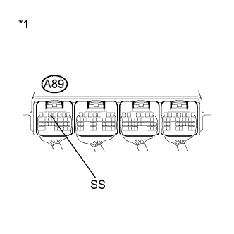
Text in Illustration *1 Component with harness connected
(Skid Control ECU)
Reconnect the skid control ECU connector and the brake stroke simulator cylinder connector.
-
Turn the power switch on (IG).
-
Measure the voltage according to the value(s) in the table below.
Standard Voltage Tester Connection Condition Specified Condition A89-5 (SS) - Body ground Brake pedal depressed approximately 1.5 seconds after power switch on (IG) Below 1.5 V
NG
REPLACE SKID CONTROL ECU Click here
OK
-
-
RECONFIRM DTC
-
Turn the power switch off.
-
Clear the DTCs Click here.
-
Turn the power switch on (READY).
-
Check if the same DTC is recorded Click here.
Result Result Proceed to DTC (C1319/35) is not output A DTC (C1319/35) is output B
B
REPLACE SKID CONTROL ECU Click here
A 
CHECK FOR INTERMITTENT PROBLEMS Click here
-