ELECTRONICALLY CONTROLLED BRAKE SYSTEM, Diagnostic DTC:C1311/11, C1312/12, C1313/13, C1314/14

| DTC Code | DTC Name |
|---|---|
| C1311/11 | Open in Main Relay 1 Circuit |
| C1312/12 | Short in Main Relay 1 Circuit |
| C1313/13 | Open in Main Relay 2 Circuit |
| C1314/14 | Short in Main Relay 2 Circuit |
DESCRIPTION
The ABS main relay 1 supplies power to the changeover solenoid and the linear solenoid.
The ABS main relay remains on for approximately 2 minutes after the power switch is turned off and the input of brake pedal operation signals stops, and supplies power to the system to keep it ready to operate.
| DTC Code | INF Code | DTC Detection Condition | Trouble Area |
|---|---|---|---|
| C1311/11 | 1 | Either of the following is detected:
|
|
| C1312/12 | 3 | Relay contact is on (BS01 terminal is 6.5 V or more) for at least 1 second when ABS main relay 1 is off. | ↑ |
| C1313/13 | 4 | Either of the following is detected:
|
|
| C1314/14 | 6 | Relay contact is on (BS02 terminal is 6.5 V or more) for at least 1 second when ABS main relay 2 is off. | ↑ |
WIRING DIAGRAM
Refer to DTCs C1241/41 and C1242/42 Click here.
INSPECTION PROCEDURE
Note
When replacing the skid control ECU, perform initialization and calibration of the linear solenoid valve Click here.
PROCEDURE
-
PERFORM ACTIVE TEST USING INTELLIGENT TESTER (ABS MAIN RELAY)
-
Connect the intelligent tester to the DLC3.
-
Turn the power switch on (IG).
-
Select the Active Test on the intelligent tester Click here.
ABS/VSC/TRC Tester Display Test Part Control Range Diagnostic Note ECB* Main Relay ABS main relay Relay ON/OFF - ECB* Main Relay2 ABS main relay 2 Relay ON/OFF - *: Electronically Controlled Brake System
-
Select the Data List on the intelligent tester Click here.
ABS/VSC/TRC Tester Display Measurement Item/Range Normal Condition Diagnostic Note ECB* Main Relay ABS main relay / ON or OFF ON: Main relay ON
OFF: Main relay OFF
- ECB* Main Relay2 ABS main relay 2 / ON or OFF ON: Main relay ON
OFF: Main relay OFF
- *: Electronically Controlled Brake System
-
Check the operating condition of the ABS main relay when operating it using the intelligent tester.
Result Result Proceed to ABS main relay in the Data List turns ON/OFF using the Active Test A ABS main relay in the Data List does not change using the Active Test B
B 
INSPECT ECB* MAIN FUSES Click here
A 
-
-
INSPECT SKID CONTROL ECU (BS TERMINAL)
-

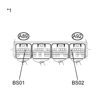
Text in Illustration *1 Component with harness connected
(Skid Control ECU)
Measure the voltage according to the value(s) in the table below.
Standard Voltage Tester Connection Switch Condition Specified Condition A89-3 (BS01) - Body ground Power switch on (IG) 8.8 to 14 V A92-7 (BS02) - Body ground Power switch on (IG) 8.8 to 14 V
NG 
REPAIR OR REPLACE HARNESS OR CONNECTOR (BS CIRCUIT)
OK
-
-
RECONFIRM DTC
-
Turn the power switch off.
-
Clear the DTCs Click here.
-
Turn the power switch on (IG).
-
Check if the same DTC is recorded Click here.
Result Result Proceed to DTCs (C1311/11, C1312/12, C1313/13 and C1314/14) are not output A DTCs (C1311/11, C1312/12, C1313/13 and/or C1314/14) are output B
B
REPLACE SKID CONTROL ECU Click here
A 
CHECK FOR INTERMITTENT PROBLEMS Click here
-
-
INSPECT ECB* MAIN FUSES
-
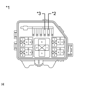
Text in Illustration *1 Engine Room No. 3 Relay Block *2 ECB* MAIN NO. 1 Fuse *3 ECB* MAIN NO. 2 Fuse Turn the power switch off.
-
Remove the ECB* MAIN NO. 1 and ECB* MAIN NO. 2 fuses from the engine room No. 3 relay block.
-
Measure the resistance according to the value(s) in the table below.
Standard Resistance Tester Connection Condition Specified Condition ECB* MAIN NO. 1 (10 A) fuse Always Below 1 Ω ECB* MAIN NO. 2 (10 A) fuse Always Below 1 Ω *: Electronically Controlled Brake System
NG
REPLACE ECB* MAIN FUSES
OK
-
-
INSPECT SKID CONTROL ECU (+BI TERMINAL)
-
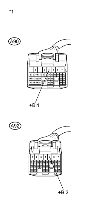
Text in Illustration *1 Front view of wire harness connector
(to Skid Control ECU)
Install the ECB* MAIN NO. 1 and ECB* MAIN NO. 2 fuses.
-
Make sure that there is no looseness at the locking part and the connecting part of the connectors.
-
Disconnect the skid control ECU connectors.
-
Measure the voltage according to the value(s) in the table below.
Standard Voltage Tester Connection Condition Specified Condition A90-4 (+BI1) - Body ground Always 11 to 14 V A92-5 (+BI2) - Body ground Always 11 to 14 V *: Electronically Controlled Brake System
NG
REPAIR OR REPLACE HARNESS OR CONNECTOR (+BI CIRCUIT)
OK
-
-
INSPECT SKID CONTROL ECU (BS TERMINAL)
-
Text in Illustration *1 Component with harness connected
(Skid Control ECU)
Reconnect the skid control ECU connectors.
-
Measure the voltage according to the value(s) in the table below.
Standard Voltage Tester Connection Switch Condition Specified Condition A89-3 (BS01) - Body ground Power switch on (IG) 8.8 to 14 V A92-7 (BS02) - Body ground Power switch on (IG) 8.8 to 14 V
NG
REPAIR OR REPLACE HARNESS OR CONNECTOR (BS CIRCUIT)
OK
REPLACE SKID CONTROL ECU Click here
-