ELECTRONICALLY CONTROLLED BRAKE SYSTEM, Diagnostic DTC:C1377/43

| DTC Code | DTC Name |
|---|---|
| C1377/43 | Capacitor Malfunction |
DESCRIPTION
The brake control power supply (capacitor) is used as auxiliary power for brake control when the auxiliary battery voltage is low.
| DTC Code | INF Code | DTC Detection Condition | Trouble Area |
|---|---|---|---|
| C1377/43 | 101 | Either of the following is detected:
|
Brake control power supply |
| ↑ | 102 | Either of the following is detected:
|
↑ |
| ↑ | 103 | Either of the following is detected:
|
Apply high voltage |
| ↑ | 105 | Either of the following is detected:
|
Brake control power supply |
| ↑ | 106 | Either of the following is detected:
|
↑ |
| ↑ | 108 | Either of the following is detected:
|
↑ |
| ↑ | 109 | Either of the following is detected:
|
|
| ↑ | 110 | Either of the following is detected:
|
Brake control power supply circuit |
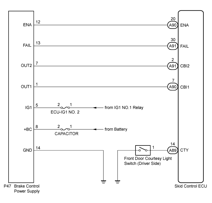
WIRING DIAGRAM
INSPECTION PROCEDURE
Note
When replacing the skid control ECU, perform initialization and calibration of the linear solenoid valve Click here.
PROCEDURE
-
CHECK FREEZE FRAME DATA
-
Check the INF code from the Freeze Frame Data memorized when the DTC (C1377/43) is stored Click here.
Result Result Proceed to INF codes (109 and/or 110) are output A INF codes (101, 102, 105, 106 and/or 108) are output B INF code (103) is output C
B 
REPLACE BRAKE CONTROL POWER SUPPLY Click here
C 
CHECK AUXILIARY BATTERY Click here
A 
-
-
INSPECT CAPACITOR FUSE
-
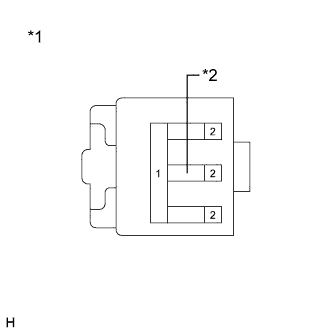
Text in Illustration *1 Fuse Box *2 CAPACITOR Fuse Remove the CAPACITOR fuse from the fuse box.
-
Measure the resistance according to the value(s) in the table below.
Standard Resistance Tester Connection Condition Specified Condition CAPACITOR (10 A) fuse Always Below 1 Ω
NG
REPLACE CAPACITOR FUSE
OK
-
-
INSPECT BRAKE CONTROL POWER SUPPLY (+BC TERMINAL)
-
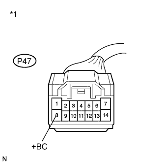
Text in Illustration *1 Front view of wire harness connector
(to Brake Control Power Supply)
Install the CAPACITOR fuse.
-
Make sure that there is no looseness at the locking part and the connecting part of the connector.
-
Disconnect the brake control power supply connector.
-
Measure the voltage according to the value(s) in the table below.
Standard Voltage Tester Connection Condition Specified Condition P47-8 (+BC) - Body ground Always 11 to 14 V
NG
REPAIR OR REPLACE HARNESS OR CONNECTOR (+BC CIRCUIT)
OK
-
-
INSPECT BRAKE CONTROL POWER SUPPLY (GND TERMINAL)
-
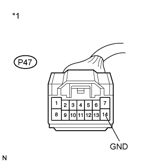
Text in Illustration *1 Front view of wire harness connector
(to Brake Control Power Supply)
Measure the resistance according to the value(s) in the table below.
Standard Resistance Tester Connection Condition Specified Condition P47-14 (GND) - Body ground Always Below 1 Ω
NG
REPAIR OR REPLACE HARNESS OR CONNECTOR (GND CIRCUIT)
OK
-
-
INSPECT BRAKE CONTROL POWER SUPPLY (CAPACITOR POWER SUPPLY OUTPUT)
-
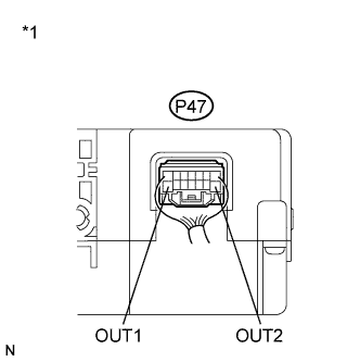
Text in Illustration *1 Component with harness connected
(Brake Control Power Supply)
Reconnect the brake control power supply connector.
-
Turn the power switch on (IG).
-
Measure the voltage according to the value(s) in the table below.
Standard Voltage Tester Connection Switch Condition Specified Condition P47-1 (OUT1) - Body ground Power switch on (IG) 11 to 14 V P47-7 (OUT2) - Body ground Power switch on (IG) 11 to 14 V
NG
REPLACE BRAKE CONTROL POWER SUPPLY Click here
OK
-
-
INSPECT SKID CONTROL ECU (CAPACITOR POWER SUPPLY INPUT)
-
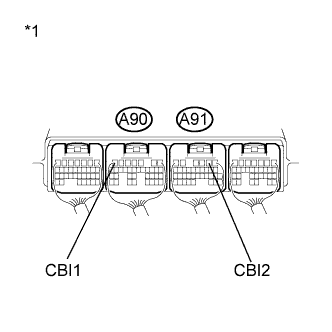
Text in Illustration *1 Component with harness connected
(Skid Control ECU)
Reconnect the skid control ECU connectors.
-
Turn the power switch on (IG).
-
Measure the voltage according to the value(s) in the table below.
Standard Voltage Tester Connection Switch Condition Specified Condition A90-7 (CBI1) - Body ground Power switch on (IG) 8.8 to 14 V A91-2 (CBI2) - Body ground Power switch on (IG) 8.8 to 14 V
NG
REPLACE SKID CONTROL ECU Click here
OK
-
-
RECONFIRM DTC
-
Turn the power switch off.
-
Clear the DTCs Click here.
-
Turn the power switch on (IG).
-
Check if the same DTC is recorded Click here.
Result Result Proceed to DTC (C1377/43) is not output A DTC (C1377/43) is output B
B
REPLACE SKID CONTROL ECU Click here
A 
CHECK FOR INTERMITTENT PROBLEMS Click here
-
-
CHECK AUXILIARY BATTERY
-
Check the auxiliary battery voltage.
Standard Voltage 11 to 14 V
NG
CHARGE OR REPLACE AUXILIARY BATTERY
OK
-
-
INSPECT BRAKE CONTROL POWER SUPPLY (+BC TERMINAL)
-
Text in Illustration *1 Front view of wire harness connector
(to Brake Control Power Supply)
Make sure that there is no looseness at the locking part and the connecting part of the connector.
-
Disconnect the brake control power supply connector.
-
Measure the voltage according to the value(s) in the table below.
Standard Voltage Tester Connection Condition Specified Condition P47-8 (+BC) - Body ground Always 11 to 14 V
NG
REPAIR OR REPLACE HARNESS OR CONNECTOR (+BC CIRCUIT)
OK
-
-
INSPECT BRAKE CONTROL POWER SUPPLY (GND TERMINAL)
-
Text in Illustration *1 Front view of wire harness connector
(to Brake Control Power Supply)
Measure the resistance according to the value(s) in the table below.
Standard Resistance Tester Connection Condition Specified Condition P47-14 (GND) - Body ground Always Below 1 Ω
NG
REPAIR OR REPLACE HARNESS OR CONNECTOR (GND CIRCUIT)
OK
REPLACE BRAKE CONTROL POWER SUPPLY Click here
-