ELECTRONICALLY CONTROLLED BRAKE SYSTEM, Diagnostic DTC:C1202/68

| DTC Code | DTC Name |
|---|---|
| C1202/68 | Master Reservoir Level Malfunction |
DESCRIPTION
When a fluid level drop in the master cylinder reservoir is detected, the signal is input to the skid control ECU.
If the DTC for the fluid level drop is memorized, the warning will be canceled and the DTC will not be stored when the fluid level returns to normal.
| DTC Code | INF Code | DTC Detection Condition | Trouble Area |
|---|---|---|---|
| C1202/68 | 511 | Either of the following is detected:
|
|
| ↑ | 512 | An open in the switch signal circuit continues for 2 seconds or more. |
|
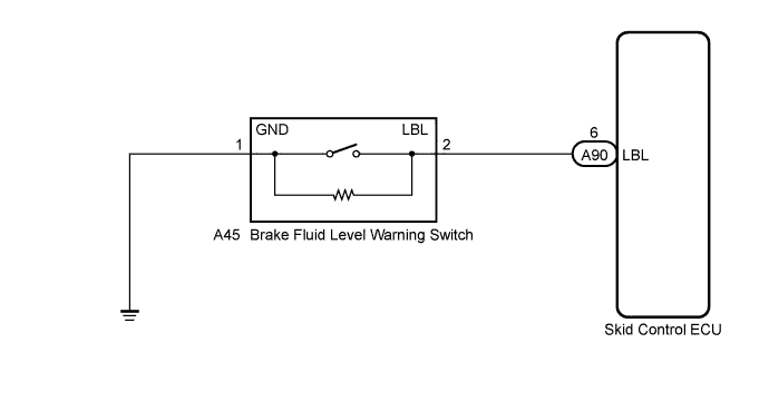
WIRING DIAGRAM
INSPECTION PROCEDURE
Note
When replacing the skid control ECU, perform initialization and calibration of the linear solenoid valve Click here.
Tech Tips
When releasing the parking brake, chock the wheels for safety.
PROCEDURE
-
CHECK BRAKE FLUID LEVEL
-
Check that the brake fluid level is sufficient.
OK Brake fluid level is sufficient. Tech Tips
-
If the fluid level drops, check for fluid leaks, and repair as necessary.
-
Check for brake fluid leakage (Connection between the brake booster pump, brake master cylinder reservoir and brake actuator, and the brake actuator and wheel cylinders).
-
If no leak exists, add and adjust fluid and then check that the trouble code is not output again.
-
-
Check that there are no leaks from the connections between the brake booster pump and brake actuator.
Tech Tips
As a visual check is very difficult, perform the check with the following procedure.
-
Bleed air from the brake actuator Click here.
-
Connect the intelligent tester to the DLC3.
-
Turn the power switch on (IG).
-
Select the Data List on the intelligent tester Click here.
ABS/VSC/TRC Tester Display Measurement Item/Range Normal Condition Diagnostic Note Accumulator Sensor Accumulator pressure sensor / Min.: 0 V, Max.: 5 V Specified value: 2.6 to 3.8 V When brake fluid is stored in the accumulator: Accumulator pressure changes in accordance with volume of fluid stored in the accumulator -
Wait a few minutes without operating the brake pedal.
-
Check that the output value of the accumulator pressure sensor does not decrease and that the pump motor is not activated due to a decrease in accumulator pressure.
OK Accumulator pressure does not decrease and the pump motor is not activated due to a decrease in accumulator pressure.
-
NG 
CHECK AND REPAIR BRAKE FLUID LEAKAGE OR ADD FLUID
OK 
-
-
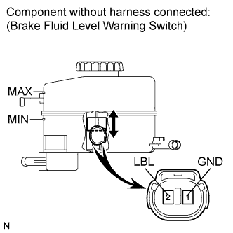
INSPECT BRAKE FLUID LEVEL WARNING SWITCH
-
Turn the power switch off.
-
Remove the reservoir filler cap and strainer.
-
Make sure that there is no looseness at the locking part and the connecting part of the connector.
-
Disconnect the brake fluid level warning switch connector.
-
Measure the resistance according to the value(s) in the table below.
Tech Tips
A float is located inside the reservoir. Its position changes according to the level of brake fluid.
Standard Resistance Tester Connection Switch Condition Specified Condition 2 (LBL) - 1 (GND) Brake fluid level warning switch OFF (Float up) 1.9 to 2.1 kΩ 2 (LBL) - 1 (GND) Brake fluid level warning switch ON (Float down) Below 1 Ω Tech Tips
If there are no problems after completing the preceding inspection, adjust the brake fluid to the MAX level with the power switch on (IG).
NG
REPLACE BRAKE MASTER CYLINDER RESERVOIR SUB-ASSEMBLY (BRAKE FLUID LEVEL WARNING SWITCH)
OK
-
-
CHECK HARNESS AND CONNECTOR (SKID CONTROL ECU - BRAKE FLUID LEVEL WARNING SWITCH)
-
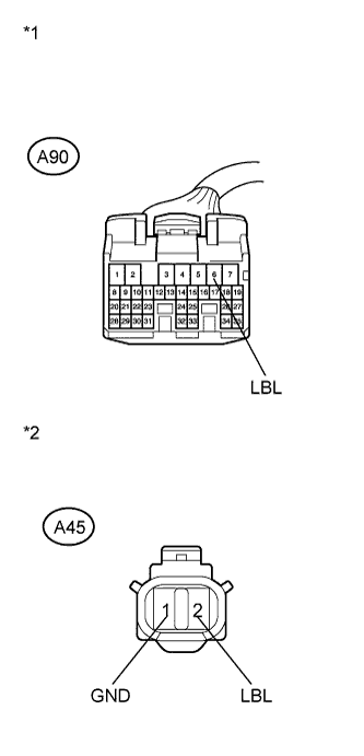
Text in Illustration *1 Front view of wire harness connector
(to Skid Control ECU)
*2 Front view of wire harness connector
(to Brake Fluid Level Warning Switch)
Make sure that there is no looseness at the locking part and the connecting part of the connector.
-
Disconnect the skid control ECU connector.
-
Measure the resistance according to the value(s) in the table below.
Standard Resistance Tester Connection Condition Specified Condition A90-6 (LBL) - A45-2 (LBL) Always Below 1 Ω A90-6 (LBL) - Body ground Always 10 kΩ or higher A45-1(GND) - Body ground Always Below 1 Ω
NG
REPAIR OR REPLACE HARNESS OR CONNECTOR
OK
-
-
INSPECT SKID CONTROL ECU (SWITCH INPUT)
-
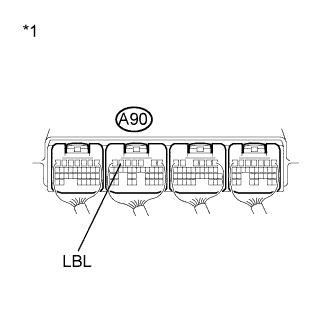
Text in Illustration *1 Component with harness connected
(Skid Control ECU)
Reconnect the skid control ECU connector and the brake fluid level warning switch connector.
-
Turn the power switch on (IG).
-
Measure the voltage according to the value(s) in the table below.
Standard Voltage Tester Connection Switch Condition Specified Condition A90-6 (LBL) - Body ground Power switch on (IG) 4 to 7 V
NG
REPLACE SKID CONTROL ECU Click here
OK
-
-
RECONFIRM DTC
-
Turn the power switch off.
-
Clear the DTCs Click here.
-
Turn the power switch on (IG).
-
Check if the same DTC is recorded Click here.
Result Result Proceed to DTC (C1202/68) is not output A DTC (C1202/68) is output B Tech Tips
If troubleshooting has been carried out according to Problem Symptoms Table, refer back to the table and proceed to the next step Click here.
B
REPLACE SKID CONTROL ECU Click here
A 
CHECK FOR INTERMITTENT PROBLEMS Click here
-