ELECTRONICALLY CONTROLLED BRAKE SYSTEM TERMINALS OF ECU

-
CHECK AUXILIARY BATTERY VOLTAGE
-
Check the auxiliary battery voltage.
-
-
SKID CONTROL ECU INSPECTION
-
Measure the voltage between each terminal or between each terminal and body ground.
-
Connect the intelligent tester to the DLC3, and check the communication condition with the skid control ECU.
-
Using an oscilloscope, check the pulse generated between each terminal or between each terminal and body ground.
Note
-
Inspection should be performed from the back of the connector with the connector connected to the skid control ECU.
-
The voltage between the terminals of the brake actuator assembly may become 0 V due to the fail safe function when the brake warning light / yellow (minor malfunction) comes on (malfunctioning).
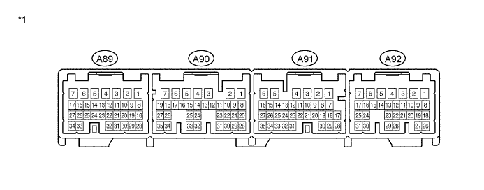
Text in Illustration *1 Component without harness connected
(Skid Control ECU)
- - Tech Tips
Inspect the ECU from the wire harness side while the connector is connected.
Terminal No. (Symbol) Wiring Color Terminal Description Condition Specified Condition A89-1 (GND) - Body ground W-B - Body ground Skid control ECU ground 1 Power switch off Below 1 Ω A89-2 (BS03) - Body ground L - Body ground Stroke simulator cut solenoid power supply output Approx. 1.5 seconds after turning power switch on (IG) 8.8 to 14 V A89-3 (BS01) - Body ground G - Body ground Master cut solenoid 1 power supply output Approx. 1.5 seconds after turning power switch on (IG) 8.8 to 14 V A89-4 (SMC1) - Body ground W - Body ground Master cut solenoid 1 output Brake pedal depressed approx. 1.5 seconds after turning power switch on (IG) Below 1.5 V A89-5 (SS) - Body ground GR - Body ground Stroke simulator cut solenoid output Brake pedal depressed approx. 1.5 seconds after turning power switch on (IG) Below 1.5 V A89-6 (FRR+) - Body ground P - Body ground Front reduction solenoid (+) RH output Power switch on (IG), after approx. 1.5 seconds brake pedal depressed → released Pulse generation
(see waveform 2)
A89-7 (FRR-) - Body ground B - Body ground Front reduction solenoid (-) RH output Approx. 1.5 seconds after turning power switch on (IG) Below 1.5 V A89-8 (E) - Body ground W - Body ground Pressure sensor 1 ground Power switch off Below 1 Ω A89-9 (VCM) - Body ground B - Body ground Pressure sensor 1 power supply output Power switch on (IG) 4.75 to 5.25 V A89-10 (SG1) - Body ground Shielded - Body ground Pressure sensor 1 shield ground Power switch off Below 1 Ω A89-11 (MR1) - Body ground Y - Body ground ABS motor relay 1 power supply output Approx. 1.5 seconds after turning power switch on (IG) 8.8 to 14 V A89-12 (SG3) - Body ground Shielded - Body ground Pressure sensor 3 shield ground Power switch off Below 1 Ω A89-13 (GS1) - Body ground Shielded - Body ground Front speed sensor RH shield ground Power switch off Below 1 Ω A89-14 (CTY) - Body ground R - Body ground Courtesy power source input Driver door close → open 8 to 16 V → Below 1 V A89-16 (RLR-) - Body ground R - Body ground Rear reduction solenoid (-) LH output Approx. 1.5 seconds after turning power switch on (IG) Below 1.5 V A89-17 (RLR+) - Body ground GR - Body ground Rear reduction solenoid (+) LH output Brake pedal depressed approx. 1.5 seconds after turning power switch on (IG) Pulse generation
(see waveform 1)
A89-18 (PRL) - Body ground W - Body ground Rear wheel cylinder pressure sensor LH input Power switch on (IG), brake pedal released 0.3 to 0.8 V A89-21 (PAC1) - Body ground Y - Body ground Accumulator pressure sensor input Power switch on (IG), after pump motor operates and stops by pedal operation 3 to 4.7 V A89-22 (FR+) - Body ground B - Body ground Front speed sensor (+) RH power supply output Vehicle speed input 8 to 15 V A89-23 (FR-) - Body ground W - Body ground Front speed sensor (-) RH input Power switch off Pulse generation
(see waveform 3)
A89-24 (R1-) - Body ground V - Body ground ABS motor relay 1 output Power switch on (IG), pump motor in operation Below 1.5 V A89-26 (RLA+) - Body ground L - Body ground Rear addition solenoid (+) LH output Brake pedal depressed approx. 1.5 seconds after turning power switch on (IG) Pulse generation
(see waveform 1)
A89-27 (RLA-) - Body ground Y - Body ground Rear addition solenoid (-) LH output Approx. 1.5 seconds after turning power switch on (IG) Below 1.5 V A89-29 (MTT) - Body ground BE - Body ground Motor relay test input Power switch on (IG), pump motor in operation 5 V or higher A89-30 (PMC1) - Body ground G - Body ground Master cylinder pressure sensor 1 input Power switch on (IG), brake pedal released 0.3 to 0.8 V A89-31 (PCK1) - Body ground BR - Body ground Pressure sensor 1 stuck check output Approx. 1.5 seconds after turning power switch on (IG) 4.75 to 5.25 V A89-32 (PFR) - Body ground L - Body ground Front wheel cylinder pressure sensor RH input Power switch on (IG), brake pedal released 0.3 to 0.8 V A89-33 (FRA-) - Body ground B - Body ground Front addition solenoid (-) RH output Approx. 1.5 seconds after turning power switch on (IG) Below 1.5 V A89-34 (FRA+) - Body ground LG - Body ground Front addition solenoid (+) RH output Brake pedal depressed approx. 1.5 seconds after turning power switch on (IG) Pulse generation
(see waveform 1)
A90-1 (GND3) - Body ground W-B - Body ground Skid control ECU ground 3 Power switch off Below 1 Ω A90-2 (IG1) - Body ground BE - Body ground IG1 power source input Power switch on (IG) 11 to 15 V A90-3 (GND2) - Body ground W-B - Body ground Skid control ECU ground 2 Power switch off Below 1 Ω A90-4 (+BI1) - Body ground L - Body ground +B power supply 1 Power switch off 11 to 15 V A90-5 (+BI3) - Body ground G - Body ground +B power supply 3 Power switch off 11 to 15 V A90-6 (LBL) - Body ground BR - Body ground Brake fluid level warning switch input Brake fluid level warning switch OFF → ON 4 to 8 V
→ Below 1.5 V
A90-7 (CBI1) - Body ground GR - Body ground Capacitor 1 power supply input Power switch on (IG) 8.8 to 14 V A90-8 (CA1H) - Body ground R - Body ground CAN communication line
(CAN No. 1 bus)
Check DTC using the intelligent tester CAN communication's DTC is not output A90-9 (CA1L) - Body ground W - Body ground CAN communication line
(CAN No. 1 bus)
Check DTC using the intelligent tester CAN communication's DTC is not output A90-10 (CA2H) - Body ground B - Body ground CAN communication line
(Power management bus)
Check DTC using the intelligent tester CAN communication's DTC is not output A90-11 (CA2L) - Body ground W - Body ground CAN communication line
(Power management bus)
Check DTC using the intelligent tester CAN communication's DTC is not output A90-12 (BZ) - Body ground BE - Body ground Skid control buzzer output Power switch on (IG), buzzer in operation Below 1 V A90-13 (VBZ) - Body ground LG - Body ground Skid control buzzer power source output Power switch on (IG) 9.1 to 14 V A90-14 (STP2) - Body ground V - Body ground Stop light control relay input Stop light switch ON → OFF
(Brake pedal depressed → released)
10 to 15 V
→ Below 1.5 V
A90-17 (GS2) - Body ground Shielded - Body ground Rear speed sensor LH shield ground Power switch off Below 1 Ω A90-19 (CSW) - Body ground B - Body ground VSC OFF switch input VSC OFF switch held ON → OFF (Released) Below 1 Ω → 10 kΩ or higher A90-20 (ENA) - Body ground R - Body ground Capacitor output Approx. 1.5 seconds after turning power switch on (IG) Pulse generation
(see waveform 6)
A90-22 (SP1) - Body ground G - Body ground Speedometer output Vehicle speed input Pulse generation
(see waveform 4)
A90-34 (RL+) - Body ground W - Body ground Rear speed sensor (+) LH power supply output Vehicle speed input 8 to 15 V A90-35 (RL-) - Body ground B - Body ground Rear speed sensor (-) LH input Power switch off Pulse generation
(see waveform 3)
A91-1 (GND5) - Body ground W-B - Body ground Skid control ECU ground 5 Power switch off Below 1 Ω A91-2 (CBI2) - Body ground W - Body ground Capacitor 2 power supply input Power switch on (IG) 8.8 to 14 V A91-3 (GND4) - Body ground W-B - Body ground Skid control ECU ground 4 Power switch off Below 1 Ω A91-4 (STPO) - Body ground V - Body ground Stop light control relay output (ACC) Power switch on (IG) 11 to 15 V A91-5 (IG2) - Body ground P - Body ground IG2 power source input Power switch on (IG) 11 to 15 V A91-7 (SGSK) - Body ground Shielded - Body ground Stroke sensor shield ground Power switch off Below 1 Ω A91-8 (SKG) - Body ground R - Body ground Stroke sensor ground Power switch off Below 1 Ω A91-10 (VCSK) - Body ground W - Body ground Stroke sensor power supply output Power switch on (IG) 3.75 to 4.95 V A91-11 (FSS) - Body ground Shielded - Body ground Front speed sensor LH shield ground Power switch off Below 1 Ω A91-12 (CANL) - Body ground W - Body ground CAN communication line
(CAN No. 3 bus)
Check DTC using the intelligent tester CAN communication's DTC is not output A91-13 (CANH) - Body ground B - Body ground CAN communication line
(CAN No. 3 bus)
Check DTC using the intelligent tester CAN communication's DTC is not output A91-16 (STP1) - Body ground B - Body ground Stop light switch input Stop light switch ON → OFF
(Brake pedal depressed → released)
10 to 15 V → Below 1.5 V A91-20 (SKS) - Body ground G - Body ground Stroke sensor 1 input Power switch on (IG), brake pedal released 0.46 to 1.35 V A91-22 (SKS2) - Body ground B - Body ground Stroke sensor 2 input Power switch on (IG), brake pedal released 2.56 to 4.35 V A91-25 (TS) - Body ground LG - Body ground Sensor check input Power switch on (IG), connect terminals TS and CG of the DLC3 → disconnect Below 1.5 V → 9.1 to 14 V A91-30 (FAIL) - Body ground G - Body ground Capacitor input Approx. 1.5 seconds after turning power switch on (IG) Pulse generation
(see waveform 5)
A91-31 (FL+) - Body ground B - Body ground Front speed sensor (+) LH power supply output Vehicle speed input 8 to 15 V A91-32 (FL-) - Body ground W - Body ground Front speed sensor (-) LH input Power switch off Pulse generation
(see waveform 3)
A92-1 (RRR-) - Body ground P - Body ground Rear reduction solenoid (-) RH output Approx. 1.5 seconds after turning power switch on (IG) Below 1.5 V A92-2 (RRR+) - Body ground BE - Body ground Rear reduction solenoid (+) RH output Brake pedal depressed approx. 1.5 seconds after turning power switch on (IG) Pulse generation
(see waveform 1)
A92-3 (GND6) - Body ground W-B - Body ground Skid control ECU ground 6 Power switch off Below 1 Ω A92-4 (SMC2) - Body ground V - Body ground Master cut solenoid 2 output Brake pedal depressed approx. 1.5 seconds after turning power switch on (IG) Below 1.5 V A92-5 (+BI2) - Body ground B - Body ground +B power supply 2 Power switch off 11 to 15 V A92-6 (+BI4) - Body ground R - Body ground +B power supply 4 Power switch off 11 to 15 V A92-7 (BS02) - Body ground L - Body ground Master cut solenoid 2 power supply output Approx. 1.5 seconds after turning power switch on (IG) 8.8 to 14 V A92-8 (FLR+) - Body ground L - Body ground Front reduction solenoid (+) LH output Power switch on (IG), after approx. 1.5 seconds, brake pedal depressed → released Pulse generation
(see waveform 2)
A92-9 (FLR-) - Body ground LG - Body ground Front reduction solenoid (-) LH output Approx. 1.5 seconds after turning power switch on (IG) Below 1.5 V A92-10 (SG2) - Body ground Shielded - Body ground Pressure sensor 2 shield ground Power switch off Below 1 Ω A92-11 (EX0)*1 - Body ground R - Body ground Stop light control relay output (ESS) Power switch on (IG) 10 to 14 V A92-12 (RSS) - Body ground Shielded - Body ground Rear speed sensor RH shield ground Power switch off Below 1 Ω A92-14 (R2-) - Body ground G - Body ground ABS motor relay 2 output Power switch on (IG), pump motor in operation Below 1.5 V A92-15 (E2) - Body ground Y - Body ground Pressure sensor 2 ground Power switch off Below 1 Ω A92-16 (VCM2) - Body ground BR - Body ground Pressure sensor 2 power supply output Power switch on (IG) 4.75 to 5.25 V A92-17 (MR2) - Body ground B - Body ground ABS motor relay 2 power supply output Approx. 1.5 seconds after turning power switch on (IG) 8.8 to 14 V A92-18 (FLA-) - Body ground V - Body ground Front addition solenoid (-) LH output Approx. 1.5 seconds after turning power switch on (IG) Below 1.5 V A92-19 (FLA+) - Body ground P - Body ground Front addition solenoid (+) LH output Brake pedal depressed approx. 1.5 seconds after turning power switch on (IG) Pulse generation
(see waveform 1)
A92-21 (RR-) - Body ground B - Body ground Rear speed sensor (-) RH input Power switch off Pulse generation
(see waveform 3)
A92-22 (RR+) - Body ground W - Body ground Rear speed sensor (+) RH power supply output Vehicle speed input 8 to 15 V A92-23 (PFL) - Body ground R - Body ground Front wheel cylinder pressure sensor LH input Power switch on (IG), brake pedal released 0.3 to 0.8 V A92-24 (PRR) - Body ground W - Body ground Rear wheel cylinder pressure sensor RH input Power switch on (IG), brake pedal released 0.3 to 0.8 V A92-26 (RRA+) - Body ground G - Body ground Rear addition solenoid (+) RH output Brake pedal depressed approx. 1.5 seconds after turning power switch on (IG) Pulse generation
(see waveform 1)
A92-27 (RRA-) - Body ground R - Body ground Rear addition solenoid (-) RH output Approx. 1.5 seconds after turning power switch on (IG) Below 1.5 V A92-28 (PMC2) - Body ground L - Body ground Master cylinder pressure sensor 2 input Power switch on (IG), brake pedal released 0.3 to 0.8 V A92-29 (PCK2) - Body ground G - Body ground Pressure sensor 2 stuck check output Power switch on (IG) 4.75 to 5.25 V *1: w/ Emergency Brake Signal
-
-
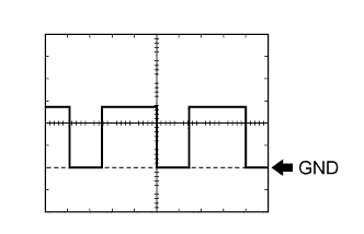
Waveform 1 (Reference): Using an oscilloscope:
Item Condition Tool setting 5 V/DIV., 50 ms./DIV. Vehicle condition Brake pedal depressed Tech Tips
Normal waveform is output only when +BI voltage is normal (11 to 14 V).
-
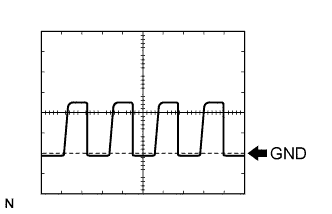
Waveform 2 (Reference): Using an oscilloscope:
Item Condition Tool setting 5 V/DIV., 50 ms./DIV. Vehicle condition Brake pedal depressed → released Tech Tips
Normal waveform is output only when +BI voltage is normal (11 to 14 V).
-
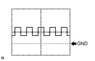
Waveform 3 (Reference): Using an oscilloscope:
Item Condition Tool setting 0.5 V/DIV., 2 ms./DIV. Vehicle condition While driving at approximately 30 km/h (18 mph) Tech Tips
As the vehicle speed (tire rotating speed) becomes faster, the cycle becomes shorter.
-
Waveform 4 (Reference): Using an oscilloscope:
Item Condition Tool setting 5 V/DIV., 50 ms./DIV. Vehicle condition While driving at approximately 20 km/h (12 mph) Tech Tips
As the vehicle speed (tire rotating speed) becomes faster, the cycle becomes shorter.
-
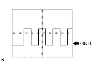
Waveform 5 (Reference): Using an oscilloscope:
Item Condition Tool setting 5 V/DIV., 200 ms./DIV. Vehicle condition Turn the power switch on (READY) -
Waveform 6 (Reference): Using an oscilloscope:
Item Condition Tool setting 2 V/DIV., 50 ms./DIV. Vehicle condition Turn the power switch on (READY)
-