ELECTRONICALLY CONTROLLED BRAKE SYSTEM, Diagnostic DTC:C1235/35, C1236/36, C1238/38, C1239/39, C1275/75, C1276/76, C1277/77, C1278/78

| DTC Code | DTC Name |
|---|---|
| C1235/35 | Foreign Object is Attached on Tip of Front Speed Sensor RH |
| C1236/36 | Foreign Object is Attached on Tip of Front Speed Sensor LH |
| C1238/38 | Foreign Object is Attached on Tip of Rear Speed Sensor RH |
| C1239/39 | Foreign Object is Attached on Tip of Rear Speed Sensor LH |
| C1275/75 | Abnormal Change in Output Signal of Front Speed Sensor RH (Test Mode DTC) |
| C1276/76 | Abnormal Change in Output Signal of Front Speed Sensor LH (Test Mode DTC) |
| C1277/77 | Abnormal Change in Output Signal of Rear Speed Sensor RH (Test Mode DTC) |
| C1278/78 | Abnormal Change in Output Signal of Rear Speed Sensor LH (Test Mode DTC) |
DESCRIPTION
When foreign matter adheres to the speed sensor tip or speed sensor rotor, these DTCs are output. An abnormal waveform input from the sensor determines these conditions.
These DTCs may be detected when a malfunction occurs in the connector terminals or wire harness of the speed sensor circuit.
DTCs C1275/75 to C1278/78 will be cleared when the speed sensor sends a wheel speed signal or when Test Mode ends. DTCs from C1275/75 to C1278/78 are output only in Test Mode.
| DTC Code | INF Code | DTC Detection Condition | Trouble Area |
|---|---|---|---|
| C1235/35 | 302 | Either of the following is detected:
|
|
| C1236/36 | 303 | Either of the following is detected:
|
|
| C1238/38 | 304 | Either of the following is detected:
|
|
| C1239/39 | 305 | Either of the following is detected:
|
|
| C1275/75 C1276/76 C1277/77 C1278/78 |
- | Detected only during Test Mode. |
|
Tech Tips
-
DTCs C1235/35 and C1275/75 are for the front speed sensor RH.
-
DTCs C1236/36 and C1276/76 are for the front speed sensor LH.
-
DTCs C1238/38 and C1277/77 are for the rear speed sensor RH.
-
DTCs C1239/39 and C1278/78 are for the rear speed sensor LH.
WIRING DIAGRAM
Refer to DTCs C0200/31, C0205/32, C0210/33 and C0215/34 Click here for front, and Click here for rear).
INSPECTION PROCEDURE
Note
When replacing the skid control ECU, perform initialization and calibration of the linear solenoid valve Click here.
Tech Tips
When C0200/31, C0205/32, C0210/33, and/or C0215/34 are output together with C1235/35, C1236/36, C1238/38, and/or C1239/39, inspect and repair the trouble areas indicated by C0200/31, C0205/32, C0210/33, and/or C0215/34 first Click here for front, or Click here for rear).
PROCEDURE
-
CHECK SPEED SENSOR AND SPEED SENSOR ROTOR SERRATIONS
-
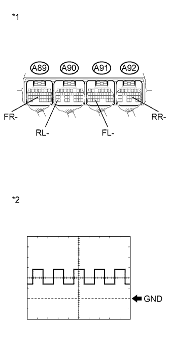
Text in Illustration *1 Component with harness connected
(Skid Control ECU)
*2 Normal Signal Waveform Connect an oscilloscope to each speed sensor terminal of the skid control ECU and body ground.
-
Check that waveform output when the wheels are rotated.
OK The same waveform is output from all the sensors and there is no noise or interference in the waveform. -
Check that the waveform does not change while jiggling a connector or a wire harness.
OK The waveform does not change. Tech Tips
-
As the vehicle speed (wheel revolution speed) increases, a cycle of the waveform narrows.
-
When noise is identified in the waveform on the oscilloscope, the erratic signals are generated due to speed sensor rotor scratches, looseness or foreign matter attached to it.
Result Result Proceed to OK A NG (except for rear 2WD) B NG (for rear 2WD) C -
B 
CHECK HARNESS AND CONNECTOR (SKID CONTROL ECU - SPEED SENSOR) Click here
C
CHECK HARNESS AND CONNECTOR (SKID CONTROL SENSOR WIRE) Click here
A 
-
-
RECONFIRM DTC
-
Turn the power switch off.
-
Clear the DTCs Click here.
-
Turn the power switch on (READY).
-
Drive the vehicle at a speed of 20 km/h (12 mph) or more for at least 15 seconds.
-
Check if the same DTC is recorded Click here.
Result Result Proceed to DTCs (C1235/35, C1236/36, C1238/38 and C1239/39) are not output A DTCs (C1235/35, C1236/36, C1238/38 and/or C1239/39) are output B
B 
REPLACE SKID CONTROL ECU Click here
A 
CHECK FOR INTERMITTENT PROBLEMS Click here
-
-
CHECK HARNESS AND CONNECTOR (SKID CONTROL ECU - SPEED SENSOR)
-
Turn the power switch off.
-
Make sure that there is no looseness at the locking part and the connecting part of the connectors.
-
Disconnect the skid control ECU connectors and the speed sensor connectors.
-
Measure the resistance according to the value(s) in the table below.
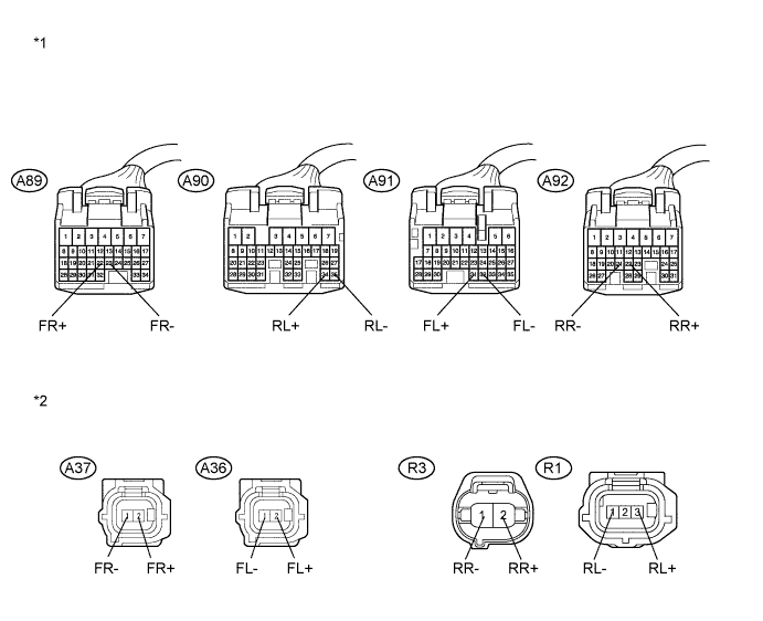
Standard Resistance for RH Tester Connection Condition Specified Condition A89-22 (FR+) - A37-2 (FR+) Always Below 1 Ω A89-22 (FR+) - Body ground Always 10 kΩ or higher A89-23 (FR-) - A37-1 (FR-) Always Below 1 Ω A89-23 (FR-) - Body ground Always 10 kΩ or higher A92-22 (RR+) - R3-2 (RR+) Always Below 1 Ω A92-22 (RR+) - Body ground Always 10 kΩ or higher A92-21 (RR-) - R3-1 (RR-) Always Below 1 Ω A92-21 (RR-) - Body ground Always 10 kΩ or higher for LH Tester Connection Condition Specified Condition A91-31 (FL+) - A36-2 (FL+) Always Below 1 Ω A91-31 (FL+) - Body ground Always 10 kΩ or higher A91-32 (FL-) - A36-1 (FL-) Always Below 1 Ω A91-32 (FL-) - Body ground Always 10 kΩ or higher A90-34 (RL+) - R1-3 (RL+) Always Below 1 Ω A90-34 (RL+) - Body ground Always 10 kΩ or higher A90-35 (RL-) - R1-1 (RL-) Always Below 1 Ω A90-35 (RL-) - Body ground Always 10 kΩ or higher Text in Illustration *1 Front view of wire harness connector
(to Skid Control ECU)
*2 Front view of wire harness connector
(to Speed Sensor)
NG
REPAIR OR REPLACE HARNESS OR CONNECTOR
OK
-
-
CHECK SPEED SENSOR AND SPEED SENSOR ROTOR
-
Remove the speed sensor and speed sensor rotor Click here and Click here for front, or Click here and Click here for rear).
-
Check the speed sensor tip and speed sensor rotor.
OK The sensor tip and rotor is free of scratches, oil, and foreign matter. Note
Check the speed sensor signal after cleaning or replacement Click here.
NG
CLEAN OR REPLACE SPEED SENSOR AND SPEED SENSOR ROTOR
OK
-
-
RECONFIRM DTC
-
Install the speed sensor and the speed sensor rotor.
-
Reconnect the skid control ECU connectors and the speed sensor connectors.
-
Clear the DTCs Click here.
-
Turn the power switch on (READY).
-
Drive the vehicle at a speed of 20 km/h (12 mph) or more for at least 15 seconds.
-
Check if the same DTC is recorded Click here.
Result Result Proceed to DTCs (C1235/35, C1236/36, C1238/38 and/or C1239/39) are output A DTCs (C1235/35, C1236/36, C1238/38 and C1239/39) are not output B
B
CHECK FOR INTERMITTENT PROBLEMS Click here
A
-
-
REPLACE SPEED SENSOR
-
Turn the power switch off.
-
Replace the front speed sensor and the rear speed sensor Click here for front, or Click here for rear).
Note
Check the speed sensor signal after replacement Click here.
NEXT
-
-
RECONFIRM DTC
-
Clear the DTCs Click here.
-
Turn the power switch on (READY).
-
Drive the vehicle at a speed of 20 km/h (12 mph) or more for at least 15 seconds.
-
Check if the same DTC is recorded Click here.
Result Result Proceed to DTCs (C1235/35, C1236/36, C1238/38 and/or C1239/39) are output A DTCs (C1235/35, C1236/36, C1238/38 and C1239/39) are not output B
B
END
A
-
-
REPLACE SPEED SENSOR ROTOR
-
Turn the power switch off.
-
Remove the front drive shaft assembly (for front) Click here.
-
Replace the front drive outboard joint shaft assembly (front speed sensor rotor) or the rear axle hub and bearing assembly (rear speed sensor rotor) Click here for front, or Click here for rear).
Tech Tips
-
If the front speed sensor rotor needs to be replaced, replace it together with the front drive outboard joint shaft assembly.
-
The rear speed sensor rotor is incorporated into the rear axle hub and bearing assembly.
If the rear speed sensor rotor needs to be replaced, replace it together with the rear axle hub and bearing assembly.
Note
Check the speed sensor signal after replacement Click here.
-
NEXT
-
-
RECONFIRM DTC
-
Install the drive shaft assembly (for front).
-
Clear the DTCs Click here.
-
Turn the power switch on (READY).
-
Drive the vehicle at a speed of 20 km/h (12 mph) or more for at least 15 seconds.
-
Check if the same DTC is recorded Click here.
Result Result Proceed to DTCs (C1235/35, C1236/36, C1238/38 and/or C1239/39) are output A DTCs (C1235/35, C1236/36, C1238/38 and C1239/39) are not output B
B
END
A
REPLACE SKID CONTROL ECU Click here
-
-
CHECK HARNESS AND CONNECTOR (SKID CONTROL SENSOR WIRE)
-
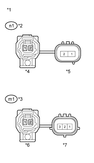
Text in Illustration *1 Front view of skid control sensor wire *2 for RH *3 for LH *4 Front view of wire harness connector
(to Sensor Side Connector "A")
*5 Front view of wire harness connector
(to Vehicle Side Connector "B")
*6 Front view of wire harness connector
(to Sensor Side Connector "C")
*7 Front view of wire harness connector
(to Vehicle Side Connector "D")
Turn the power switch off.
-
Make sure that there is no looseness at the locking part and the connecting part of the connectors.
-
Disconnect the skid control sensor wire.
-
Measure the resistance according to the value(s) in the table below.
Standard Resistance for RH Tester Connection Condition Specified Condition n1 ("A"-2) - n1 ("B"-2) Always Below 1 Ω n1 ("A"-2) - n1 ("B"-1) Always 10 kΩ or higher n1 ("A"-2) - Body ground Always 10 kΩ or higher n1 ("A"-1) - n1 ("B"-1) Always Below 1 Ω n1 ("A"-1) - n1 ("B"-2) Always 10 kΩ or higher n1 ("A"-1) - Body ground Always 10 kΩ or higher for LH Tester Connection Condition Specified Condition m1 ("C"-2) - m1 ("D"-3) Always Below 1 Ω m1 ("C"-2) - m1 ("D"-1) Always 10 kΩ or higher m1 ("C"-2) - Body ground Always 10 kΩ or higher m1 ("C"-1) - m1 ("D"-1) Always Below 1 Ω m1 ("C"-1) - m1 ("D"-3) Always 10 kΩ or higher m1 ("C"-1) - Body ground Always 10 kΩ or higher Note
Check the speed sensor signal after replacement Click here.
NG
REPLACE SKID CONTROL SENSOR WIRE Click here
OK
-
-
CHECK HARNESS AND CONNECTOR (SKID CONTROL ECU - SPEED SENSOR)
-
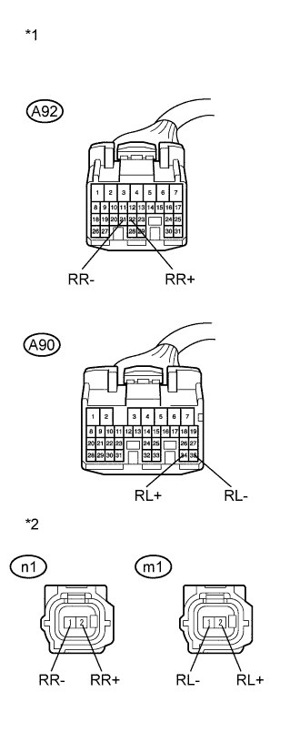
Text in Illustration *1 Front view of wire harness connector
(to Skid Control ECU)
*2 Front view of wire harness connector
(to Rear Speed Sensor)
Reconnect the skid control sensor wire (for vehicle side).
-
Make sure that there is no looseness at the locking part and the connecting part of the connectors.
-
Disconnect the skid control ECU connectors.
-
Measure the resistance according to the value(s) in the table below.
Standard Resistance for RH Tester Connection Condition Specified Condition A92-22 (RR+) - n1-2 (RR+) Always Below 1 Ω A92-22 (RR+) - Body ground Always 10 kΩ or higher A92-21 (RR-) - n1-1 (RR-) Always Below 1 Ω A92-21 (RR-) - Body ground Always 10 kΩ or higher for LH Tester Connection Condition Specified Condition A90-34 (RL+) - m1-2 (RL+) Always Below 1 Ω A90-34 (RL+) - Body ground Always 10 kΩ or higher A90-35 (RL-) - m1-1 (RL-) Always Below 1 Ω A90-35 (RL-) - Body ground Always 10 kΩ or higher
NG
REPAIR OR REPLACE HARNESS OR CONNECTOR
OK
-
-
RECONFIRM DTC
-
Reconnect the skid control ECU connectors and the skid control sensor wire (for sensor side).
-
Clear the DTCs Click here.
-
Turn the power switch on (READY).
-
Drive the vehicle at a speed of 20 km/h (12 mph) or more for at least 15 seconds.
-
Check if the same DTC is recorded Click here.
Result Result Proceed to DTCs (C1235/35, C1236/36, C1238/38 and/or C1239/39) are output A DTCs (C1235/35, C1236/36, C1238/38 and C1239/39) are not output B
B
CHECK FOR INTERMITTENT PROBLEMS Click here
A
-
-
REPLACE SPEED SENSOR AND SPEED SENSOR ROTOR
-
Turn the power switch off.
-
Replace the rear speed sensor and the rear axle hub and bearing assembly (rear speed sensor rotor) Click here.
Tech Tips
The rear speed sensor rotor is incorporated into the rear axle hub and bearing assembly.
If the rear speed sensor rotor needs to be replaced, replace it together with the rear axle hub and bearing assembly with rear speed sensor.
Note
Check the speed sensor signal after replacement Click here.
NEXT
-
-
RECONFIRM DTC
-
Clear the DTCs Click here.
-
Turn the power switch on (READY).
-
Drive the vehicle at a speed of 20 km/h (12 mph) or more for at least 15 seconds.
-
Check if the same DTC is recorded Click here.
Result Result Proceed to DTCs (C1235/35, C1236/36, C1238/38 and/or C1239/39) are output A DTCs (C1235/35, C1236/36, C1238/38 and C1239/39) are not output B
B
END
A
REPLACE SKID CONTROL ECU Click here
-