REAR ACTIVE STABILIZER CONTROL ACTUATOR INSTALLATION

-
INSTALL REAR STABILIZER BUSHING
-
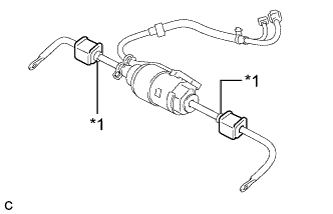
Text in Illustration *1 Stopper Install the 2 rear stabilizer bushings to the outside of the stoppers on the rear active stabilizer control actuator assembly.
-
-
INSTALL REAR NO. 1 STABILIZER BAR BRACKET
-
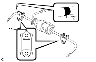
Text in Illustration *1 Identification Shape *2 Identification Mark Install the 2 rear No. 1 stabilizer bar brackets to the rear stabilizer bushings.
Note
-
Ensure that the identification shape faces upward.
-
Ensure that the identification mark is on the right side of the vehicle.
-
-
-
INSTALL REAR ACTIVE STABILIZER CONTROL ACTUATOR ASSEMBLY
-
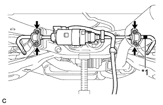
Text in Illustration *1 Identification Mark Install the rear active stabilizer control actuator assembly with 2 rear stabilizer bushings and 2 rear No. 1 stabilizer bar brackets with the 4 nuts.
- Torque:
- 75 N*m { 765 kgf*cm, 55 ft.*lbf }
Note
-
Ensure that the identification mark is on the right side of the vehicle.
-
Take care not to damage the wire harness and connectors of the rear active stabilizer control actuator assembly.
-
Avoid any impact to the rear active stabilizer control actuator assembly.
-
Do not drop the rear active stabilizer control actuator assembly. If it is dropped, replace it with a new one.
-
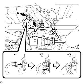
Using the procedures below, connect the connector (A).
-
Connect the connector (A).*1
-
Rotate the lever in the direction of the arrow until a "click" sound is heard.*2
-
Lock the lever's lock.*3
-
-
Engage the 2 clamps and connect the connector (B).
-
-
INSTALL NO. 2 LUGGAGE COMPARTMENT SIDE COVER PROTECTOR
-
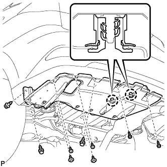
Engage the 2 craws and install the No. 2 luggage compartment side cover protector.
-
Install the 3 clips and 2 bolts.
-
Install the 4 screws.
- Torque:
- 7.5 N*m { 77 kgf*cm, 66 in.*lbf }
-
Install the 2 screws.
- Torque:
- 7.5 N*m { 77 kgf*cm, 66 in.*lbf }
-
Install a new grommet.
-
-
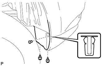
INSTALL REAR QUARTER PANEL MUDGUARD SUB-ASSEMBLY LH (w/ Rear Fender Mudguard)
-
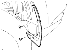
Using a 4 mm hexagon wrench, install the rear quarter panel mudguard sub-assembly with the 3 hexagon screws.
- Torque:
- 7.5 N*m { 77 kgf*cm, 66 in.*lbf }
-
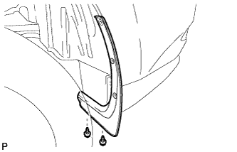
Install the 2 screws.
- Torque:
- 7.5 N*m { 77 kgf*cm, 66 in.*lbf }
-
-
INSTALL REAR STABILIZER LINK SUB-ASSEMBLY
-
Install the rear stabilizer link sub-assembly (LH Side).
-
Hold the rear lower stabilizer bracket between aluminium plates in a vise as shown in the illustration.
Note
Do not overtighten the vise.
-
Install the rear stabilizer link sub-assembly to the rear lower stabilizer bracket as shown in the illustration.
- Torque:
- 92 N*m { 938 kgf*cm, 68 ft.*lbf }
Tech Tips
If the ball joint turns together with the nut, use a hexagon wrench (6 mm) to hold the stud bolt.
-
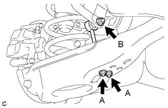
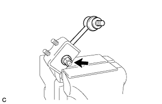
Install the rear stabilizer link sub-assembly to the rear active stabilizer control actuator assembly with the nut (B).
- Torque:
- 90 N*m { 918 kgf*cm, 66 ft.*lbf }
Tech Tips
If the ball joint turns together with the nut, use a hexagon wrench (6 mm) to hold the stud bolt.
-
Install the rear stabilizer link sub-assembly with rear lower stabilizer bracket to the rear No. 2 suspension arm assembly LH with the 2 nuts (A).
- Torque:
- 82 N*m { 836 kgf*cm, 60 ft.*lbf }
-
-
Install the rear stabilizer link sub-assembly (RH Side).
Tech Tips
Perform the same procedure as the LH side.
-