ELECTRONICALLY CONTROLLED BRAKE SYSTEM TEST MODE PROCEDURE

-
WARNING LIGHT AND INDICATOR LIGHT INITIAL CHECK
-
Release the parking brake.
Note
When releasing the parking brake, move the shift lever to P for safety.
Tech Tips
When the parking brake is applied or the brake fluid level is low, the brake warning light / red (malfunction) comes on.
-
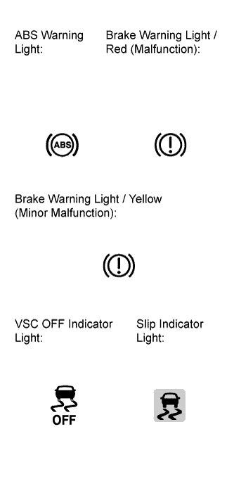
When the power switch is turned on (IG), check that the VSC OFF indicator light comes on for approximately 3 seconds, and ABS warning, brake warning / red (malfunction), brake warning / yellow (minor malfunction) and slip indicator lights remain on until the power switch is turned on (READY).
Tech Tips
-
If the skid control ECU stores any DTCs, the ABS warning, brake warning / red (malfunction), brake warning / yellow (minor malfunction) and slip indicator lights will come on.
-
If any of the indicators remains on or does not come on, proceed to troubleshooting for the light circuits listed below.
Trouble Area See Procedure ABS warning light circuit (Remains on) ABS warning light circuit (Does not come on) Brake warning light / red (malfunction) circuit (Remains on) Brake warning light / red (malfunction) circuit (Does not come on) Brake warning light / yellow (minor malfunction) circuit (Remains on) Brake warning light / yellow (minor malfunction) circuit (Does not come on) VSC OFF indicator light circuit (Remains on) VSC OFF indicator light circuit (Does not come on) Slip indicator light circuit (Remains on) Slip indicator light circuit (Does not come on) -
-
-
SENSOR CHECK USING TEST MODE (SIGNAL CHECK) (When Using the Intelligent Tester)
Note
Before performing the master cylinder pressure sensor check or yaw rate sensor zero point voltage check, perform linear valve offset learning.
Tech Tips
-
If the power switch is turned from on (IG) to on (ACC) or off during Test Mode (signal check), DTCs recorded during the sensor check will be cleared.
-
During Test Mode (signal check), the skid control ECU records all DTCs detected in the sensor check. By performing Test Mode (signal check), the codes are cleared if a normal condition is confirmed. The remaining codes are the codes where an abnormality was found.
-
Procedure to enter the Test Mode
-
Turn the power switch off.
-
Check that the steering wheel is centered.
-
Check that the shift lever is in P.
-
Connect the intelligent tester to the DLC3.
-
Turn the power switch on (IG).
-
Turn the intelligent tester on.
-
Switch the skid control ECU to Test Mode using the intelligent tester. Enter the following menus: Chassis / ABS/VSC/TRC / Signal Check.
-
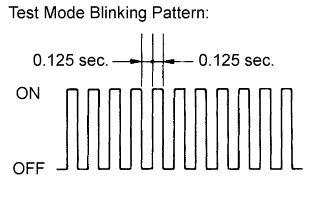
Check that the ABS warning, brake warning / yellow (minor malfunction) and slip indicator lights come on for several seconds and then blink in Test Mode.
Tech Tips
If the ABS warning, brake warning / yellow (minor malfunction) and slip indicator lights do not blink, inspect the TS and CG terminal circuit and ABS warning, brake warning / yellow (minor malfunction) and slip indicator light circuits.
-
Check the ABS sensors.
Tech Tips
Check that the ABS warning light is blinking in the Test Mode blinking pattern before performing the ABS sensor check.
-
-
Acceleration Sensor Check
-
Keep the vehicle stationary on a level surface for 2 seconds or more.
Tech Tips
The acceleration sensor check can be performed with the master cylinder pressure sensor check below.
-
-
Master Cylinder Pressure Sensor Check
Note
Before performing the master cylinder pressure sensor check, perform linear valve offset learning.
-
Leave the vehicle in a stationary condition and release the brake pedal for 1 second or more, and quickly and continuously depress the brake pedal with a force greater than 98 N (10 kgf, 22 lbf) for 1 second.
-
Check that the ABS warning light stays on for 3 seconds.
Tech Tips
-
Confirm that the ABS warning light comes on.
-
While the ABS warning light stays on, continue to depress the brake pedal with a force of 98 N (10 kgf, 22 lbf) or more.
-
The ABS warning light comes on for 3 seconds every time the preceding brake pedal operation is performed.
-
-
-
Speed Sensor Check
Note
Before performing the speed sensor check, complete the acceleration sensor and master cylinder pressure sensor checks.
-
Drive the vehicle straight-ahead.
Accelerate the vehicle to a speed of 45 km/h (28 mph) or more for several seconds and check that the ABS warning light goes off.
Tech Tips
-
The sensor check may not be completed if wheelspin occurs.
-
The ABS warning light comes on immediately if a malfunction is detected during the speed sensor check.
-
-
Stop the vehicle.
Note
-
The speed sensor check may not be completed if the speed sensor check is started while turning the steering wheel or spinning the wheels.
-
After the ABS warning light goes off, if vehicle speed exceeds 80 km/h (50 mph), a sensor check code will be stored again. Decelerate or stop the vehicle before the speed reaches 80 km/h (50 mph).
-
If the sensor check has not been completed, the ABS warning light will blink while driving and the ABS will not operate.
-
-
Check the VSC sensor.
Tech Tips
Check that the brake warning / yellow (minor malfunction) and slip indicator lights are blinking in the Test Mode blinking pattern before performing the VSC sensor check.
-
-
Yaw Rate Sensor Zero Point Voltage Check
Note
Before performing the yaw rate sensor zero point voltage check, perform linear valve offset learning.
-
Keep the vehicle stationary on a level surface for 4 seconds or more.
-
-
Yaw Rate Sensor Output Check
-
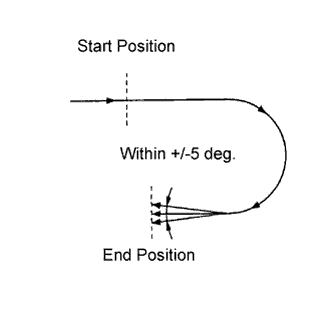
Move the shift lever from P to D and drive the vehicle at a speed of approximately 5 km/h (3 mph), and turn the steering wheel either to the left or right 90° or more until the vehicle makes a 180° turn.
Note
-
Make a 180° turn. At the end of the turn, the direction of the vehicle should be within 180° +/-5° of its start position.
-
Do not allow the wheels to spin.
-
Do not turn the power switch off while turning.
-
Do not move the shift lever to P while turning, but changing the vehicle speed, stopping, or driving in reverse is acceptable.
-
-
Stop the vehicle and move the shift lever to P. Check that the skid control buzzer sounds for 3 seconds.
Tech Tips
-
If the skid control buzzer sounds, the sensor check has completed normally.
-
If the skid control buzzer does not sound, check the skid control buzzer circuit Click here, then perform the sensor check again.
-
If the skid control buzzer still does not sound, the yaw rate sensor may be malfunctioning. Check for DTCs.
-
-
-
End of Sensor Check
-
If the sensor check is completed, the ABS warning light blinks (Test Mode) when the vehicle is stopped and goes off while driving.
Note
-
When all the yaw rate and acceleration sensor, speed sensor, and master cylinder pressure sensor checks are completed, the sensor check is completed.
-
If the sensor check has not been completed, the ABS warning light will blink while driving and the ABS will not operate.
-
-
-
Read Sensor Check DTCs
-
Read the DTC(s) by following the intelligent tester screen.
Note
-
If only DTCs other than Test Mode sensor check DTCs are displayed, repair the malfunction and clear the DTCs.
-
If Test Mode sensor check DTCs and other DTCs are displayed or if only Test Mode sensor check DTCs are displayed, repair the malfunction, clear the DTCs, and perform the Test Mode inspection again.
Tech Tips
See "Sensor Check DTCs".
-
-
Turn the power switch off and disconnect the intelligent tester.
-
-
Sensor Check DTCs
ABS Sensor DTC Code Detection Item Trouble Area C1271 Low Output Signal of Front Speed Sensor RH
-
Front speed sensor RH
-
Sensor installation
-
Speed sensor rotor
C1272 Low Output Signal of Front Speed Sensor LH
-
Front speed sensor LH
-
Sensor installation
-
Speed sensor rotor
C1273 Low Output Signal of Rear Speed Sensor RH
-
Rear speed sensor RH
-
Sensor installation
-
Speed sensor rotor
C1274 Low Output Signal of Rear Speed Sensor LH
-
Rear speed sensor LH
-
Sensor installation
-
Speed sensor rotor
C1275 Abnormal Change in Output Signal of Front Speed Sensor RH
-
Front speed sensor RH
-
Speed sensor rotor
C1276 Abnormal Change in Output Signal of Front Speed Sensor LH
-
Front speed sensor LH
-
Speed sensor rotor
C1277 Abnormal Change in Output Signal of Rear Speed Sensor RH
-
Rear speed sensor RH
-
Speed sensor rotor
C1278 Abnormal Change in Output Signal of Rear Speed Sensor LH
-
Rear speed sensor LH
-
Speed sensor rotor
C1279 Acceleration Sensor Output Voltage Malfunction
-
Sensor installation
-
Yaw rate and acceleration sensor
C1281 Master Cylinder Pressure Sensor Output Malfunction
-
Stop light switch
-
Master cylinder pressure sensor
VSC Sensor DTC Code Detection Item Trouble Area C0371 Yaw Rate Sensor
-
Sensor installation
-
Yaw rate and acceleration sensor
Electronically Controlled Brake System Sensor DTC Code Detection Item Trouble Area C1346 Stroke Sensor Zero Point Learning Malfunction
-
Brake pedal stroke sensor
-
Brake pedal stroke sensor circuit
Tech Tips
The codes in this table are output only in Test Mode (signal check).
-
-
-
SENSOR CHECK USING TEST MODE (SIGNAL CHECK) (When not Using the Intelligent Tester)
Note
Before performing the master cylinder pressure sensor check or yaw rate sensor zero point voltage check, perform linear valve offset learning.
Tech Tips
-
If the power switch is turned from on (IG) to on (ACC) or off during Test Mode (signal check), DTCs recorded during the sensor check will be cleared.
-
During Test Mode (signal check), the skid control ECU records all DTCs detected in the sensor check. By performing Test Mode (signal check), the codes are cleared if a normal condition is confirmed. The remaining codes are the codes where an abnormality was found.
-
Procedure to enter Test Mode
-
Turn the power switch off.
-
Check that the steering wheel is centered.
-
Check that the shift lever is in P.
-
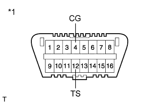
Text in Illustration *1 Front view of DLC3 Using SST, connect terminals TS and CG of the DLC3.
- SST
- 09843-18040
-
Turn the power switch on (IG).
-
Check that the ABS warning, brake warning / yellow (minor malfunction) and slip indicator lights come on for several seconds and then blink in Test Mode.
Tech Tips
If the ABS warning, brake warning / yellow (minor malfunction) and slip indicator lights do not blink, inspect the TS and CG terminal circuit and ABS warning, brake warning / yellow (minor malfunction) and slip indicator light circuits.
-
Check the ABS sensors.
Tech Tips
Check that the ABS warning light is blinking in the Test Mode blinking pattern before performing the ABS sensor check.
-
-
Acceleration Sensor Check
-
Keep the vehicle stationary on a level surface for 2 seconds or more.
Tech Tips
The acceleration sensor check can be performed with the master cylinder pressure sensor check below.
-
-
Master Cylinder Pressure Sensor Check
Note
Before performing the master cylinder pressure sensor check, perform linear valve offset learning.
-
Leave the vehicle in a stationary condition and release the brake pedal for 1 second or more, and quickly and continuously depress the brake pedal with a force greater than 98 N (10 kgf, 22 lbf) for 1 second.
-
Check that the ABS warning light stays on for 3 seconds.
Tech Tips
-
Confirm that the ABS warning light comes on.
-
While the ABS warning light stays on, continue to depress the brake pedal with a force of 98 N (10 kgf, 22 lbf) or more.
-
The ABS warning light comes on for 3 seconds every time the preceding brake pedal operation is performed.
-
-
-
Speed Sensor Check
Note
Before performing the speed sensor check, complete the acceleration sensor and master cylinder pressure sensor checks.
-
Drive the vehicle straight-ahead.
Accelerate the vehicle to a speed of 45 km/h (28 mph) or more for several seconds and check that the ABS warning light goes off.
Tech Tips
-
The sensor check may not be completed if wheelspin occurs.
-
The ABS warning light comes on immediately if a malfunction is detected during the speed sensor check.
-
-
Stop the vehicle.
Note
-
The speed sensor check may not be completed if the speed sensor check is started while turning the steering wheel or spinning the wheels.
-
After the ABS warning light goes off, if vehicle speed exceeds 80 km/h (50 mph), a sensor check code will be stored again. Decelerate or stop the vehicle before the speed reaches 80 km/h (50 mph).
-
If the sensor check has not been completed, the ABS warning light will blink while driving and the ABS will not operate.
-
-
Check the VSC sensor.
Tech Tips
Check that the brake warning / yellow (minor malfunction) and slip indicator lights are blinking in the Test Mode blinking pattern before performing the VSC sensor check.
-
-
Yaw Rate Sensor Zero Point Voltage Check
Note
Before performing the yaw rate sensor zero point voltage check, perform linear valve offset learning.
-
Keep the vehicle stationary on a level surface for 4 seconds or more.
-
-
Yaw Rate Sensor Output Check
-
Move the shift lever from P to D and drive the vehicle at a speed of approximately 5 km/h (3 mph), and turn the steering wheel either to the left or right 90° or more until the vehicle makes a 180° turn.
Note
-
Make a 180° turn. At the end of the turn, the direction of the vehicle should be within 180° +/-5° of its start position.
-
Do not allow the wheels to spin.
-
Do not turn the power switch off while turning.
-
Do not move the shift lever to P while turning, but changing the vehicle speed, stopping, or driving in reverse is acceptable.
-
-
Stop the vehicle and move the shift lever to P. Check that the skid control buzzer sounds for 3 seconds.
Tech Tips
-
If the skid control buzzer sounds, the sensor check has completed normally.
-
If the skid control buzzer does not sound, check the skid control buzzer circuit Click here, then perform the sensor check again.
-
If the skid control buzzer still does not sound, the yaw rate sensor may be malfunctioning. Check for DTCs.
-
-
-
End of Sensor Check
-
If the sensor check is completed, the ABS warning light blinks (Test Mode) when the vehicle is stopped and goes off while driving.
Note
-
When the yaw rate sensor, acceleration sensor, speed sensor, and master cylinder pressure sensor checks are completed, the sensor check is completed.
-
If the sensor check has not been completed, the ABS warning light will blink while driving and the ABS will not operate.
-
-
-
Read Sensor Check DTCs
-
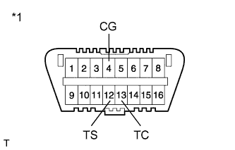
Text in Illustration *1 Front view of DLC3 Using SST, connect terminals TC and CG of the DLC3.
- SST
- 09843-18040
-
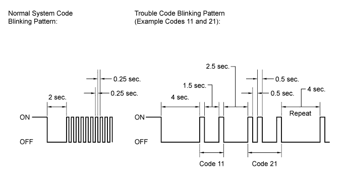
Count the number of blinks of the ABS warning, brake warning / yellow (minor malfunction) and slip indicator lights.
Note
-
If only DTCs other than the Test Mode sensor check DTCs are displayed, repair the malfunctions and clear the DTCs.
-
If Test Mode sensor check DTCs and other DTCs are displayed or if only the Test Mode sensor check DTCs are displayed, repair the malfunctions, clear the DTCs, and perform the Test Mode inspection again.
Tech Tips
-
If more than 1 malfunction is detected at the same time, the lowest numbered code will be displayed first.
-
See "Sensor Check DTCs".
-
-
After performing the check, disconnect SST from terminals TS and CG, and TC and CG of the DLC3 and turn the power switch off.
-
Turn the power switch on (IG).
Tech Tips
-
If the power switch is not turned on (IG) after SST is removed from the DLC3, the previous Test Mode will continue.
-
If the power switch is turned on (IG) with terminals TS and CG connected, the previous Test Mode will continue.
-
-
-
Sensor Check DTCs
ABS Sensor DTC Code Detection Item Trouble Area 71 Low Output Signal of Front Speed Sensor RH
-
Front speed sensor RH
-
Sensor installation
-
Speed sensor rotor
72 Low Output Signal of Front Speed Sensor LH
-
Front speed sensor LH
-
Sensor installation
-
Speed sensor rotor
73 Low Output Signal of Rear Speed Sensor RH
-
Rear speed sensor RH
-
Sensor installation
-
Speed sensor rotor
74 Low Output Signal of Rear Speed Sensor LH
-
Rear speed sensor LH
-
Sensor installation
-
Speed sensor rotor
75 Abnormal Change in Output Signal of Front Speed Sensor RH
-
Front speed sensor RH
-
Speed sensor rotor
76 Abnormal Change in Output Signal of Front Speed Sensor LH
-
Front speed sensor LH
-
Speed sensor rotor
77 Abnormal Change in Output Signal of Rear Speed Sensor RH
-
Rear speed sensor RH
-
Speed sensor rotor
78 Abnormal Change in Output Signal of Rear Speed Sensor LH
-
Rear speed sensor LH
-
Speed sensor rotor
79 Acceleration Sensor Output Voltage Malfunction
-
Sensor installation
-
Yaw rate and acceleration sensor
81 Master Cylinder Pressure Sensor Output Malfunction
-
Stop light switch
-
Master cylinder pressure sensor
VSC Sensor DTC Code Detection Item Trouble Area 71 Yaw Rate Sensor
-
Sensor installation
-
Yaw rate and acceleration sensor
Electronically Controlled Brake System Sensor DTC Code Detection Item Trouble Area 71 Stroke Sensor Zero Point Learning Malfunction
-
Brake pedal stroke sensor
-
Brake pedal stroke sensor circuit
Tech Tips
The codes in this table are output only in Test Mode (signal check).
-
-