REAR SHOCK ABSORBER INSTALLATION

Tech Tips
-
Use the same procedure for the RH side and LH side.
-
The procedure listed below is for the LH side.
-
TEMPORARILY TIGHTEN REAR SHOCK ABSORBER ASSEMBLY
-
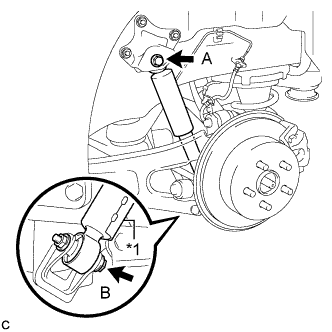
Text in Illustration *1 Protector Temporarily tighten the rear shock absorber assembly with the bolt (B), nut, and bolt (A).
Note
-
Ensure that the protector faces the front of the vehicle.
-
Since the stopper nut is used, tighten the bolt (B).
-
Fully tighten the bolts after stabilizing the suspension.
-
-
Slowly lower the rear No. 2 suspension arm assembly.
-
-
STABILIZE SUSPENSION
-
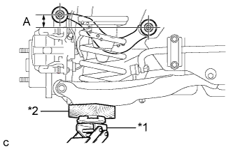
Text in Illustration *1 Jack *2 Wooden Block Jack up the rear No. 2 suspension arm assembly, placing a wooden block underneath to avoid damage. Apply load to the suspension so that the rear upper control arm assembly is positioned as shown in the illustration.
Standard length (A) 24.3 mm (0.957 in.) CAUTION:
Do not jack up the rear No. 2 suspension arm assembly too high as the vehicle may fall.
Tech Tips
-
If the rear upper control arm assembly cannot be positioned as shown in the illustration even when the rear No. 2 suspension arm assembly is jacked up, apply additional load such as by placing a weight in the luggage compartment.
-
Use the same procedure for the RH side and LH side.
-
-
-
FULLY TIGHTEN REAR SHOCK ABSORBER ASSEMBLY
-

Fully tighten the bolt (B) and bolt (A).
- Torque:
- Bolt (A)
- 100 N*m { 1020 kgf*cm, 74 ft.*lbf }
- Bolt (B)
- 92 N*m { 938 kgf*cm, 68 ft.*lbf }
Note
-
Since the stopper nut is used, tighten the bolt (B).
-
The final torque must be applied under the standard vehicle height conditions.
-
-
INSTALL REAR SUSPENSION ARM COVER (w/o Air Suspension)
-
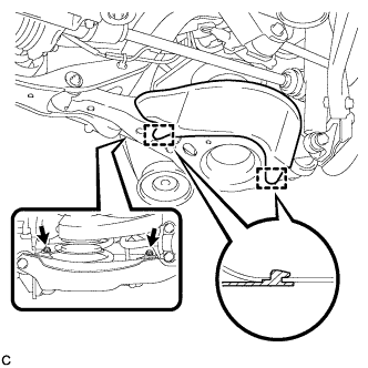
Insert the 2 guides of the rear suspension arm cover to the rear No. 2 suspension arm assembly.
-
Install the rear suspension arm cover to the rear No. 2 suspension arm assembly with the 2 bolts as shown in the illustration.
- Torque:
- 12 N*m { 122 kgf*cm, 9 ft.*lbf }
Note
Make sure that the 2 guides of rear suspension arm cover are inserted.
-
-
INSTALL REAR SUSPENSION ARM COVER (w/ Air Suspension)
-
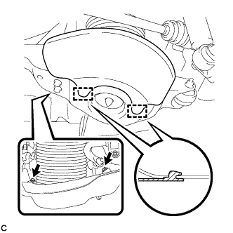
Insert the 2 guides of the rear suspension arm cover to the rear No. 2 suspension arm assembly.
-
Install the rear suspension arm cover to the rear No. 2 suspension arm assembly with the 2 bolts as shown in the illustration.
- Torque:
- 12 N*m { 122 kgf*cm, 9 ft.*lbf }
Note
Make sure that the 2 guides of rear suspension arm cover are inserted.
-
Check that the rear pneumatic cylinder cover is not deformed or collapsed inward.
-
-
INSTALL REAR WHEEL
- Torque:
- 103 N*m { 1050 kgf*cm, 76 ft.*lbf }