FRONT SUSPENSION MEMBER REMOVAL

Tech Tips
-
Use the same procedure for RHD and LHD vehicles.
-
The procedure listed below is for the LHD vehicle.
-
REMOVE ENGINE ASSEMBLY WITH TRANSAXLE
Tech Tips
Refer to the procedure up to Remove Engine Assembly with Transaxle Click here.
-
REMOVE FRONT NO. 1 STABILIZER BRACKET LH (w/o Active Stabilizer System)
-
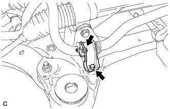
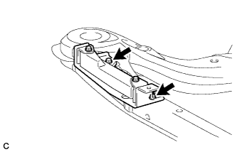
Remove the 2 bolts and front No. 1 stabilizer bracket LH from the front frame assembly.
-
-
REMOVE FRONT NO. 1 STABILIZER BRACKET RH (w/o Active Stabilizer System)
Tech Tips
Perform the same procedure as the LH side.
-
REMOVE FRONT STABILIZER BAR WITH FRONT STABILIZER LINK ASSEMBLY (w/o Active Stabilizer System)
-
Remove the front stabilizer bar with front stabilizer link assembly.
-
-
REMOVE FRONT NO. 1 STABILIZER BRACKET LH (w/ Active Stabilizer System)
-
Remove the 2 bolts and front No. 1 stabilizer bracket LH from the front frame assembly.
-
-
REMOVE FRONT NO. 1 STABILIZER BRACKET RH (w/ Active Stabilizer System)
Tech Tips
Perform the same procedure as the LH side.
-
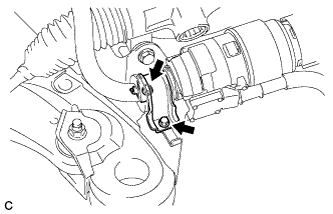
REMOVE FRONT ACTIVE STABILIZER CONTROL ACTUATOR ASSEMBLY (w/ Active Stabilizer System)
-
Remove the front active stabilizer control actuator assembly with front stabilizer link assembly.
-
-
REMOVE STEERING LINK ASSEMBLY
-
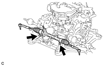
Remove the 2 bolts, 2 nuts and steering link assembly.
Note
Because the nut has its own stopper, do not turn the nut. Loosen the bolt with the nut secured.
-
-
SEPARATE FRONT FRAME ASSEMBLY
-
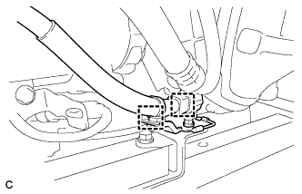
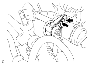
Disconnect the 2 clamps and engine wire from the front frame assembly.
-
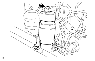
Remove the bolt and HV transaxle mass damper.
-
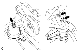
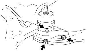
Remove the 2 nuts and separate the engine mounting insulators LH and RH.
-
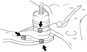
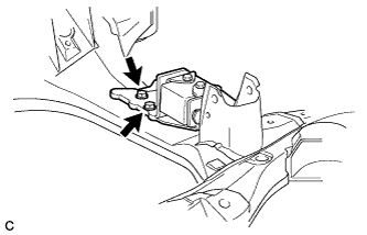
Remove the nut and separate the front engine mounting insulator.
-
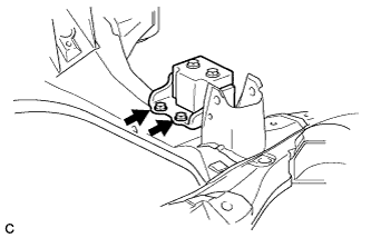
Remove the 2 bolts and separate the rear engine mounting insulator.
Note
Do not remove the rear engine mounting insulator assembly through bolts. Doing so makes it difficult to install the rear engine mounting insulator assembly.
-
Remove the front frame assembly.
-
-
REMOVE FRONT ENGINE MOUNTING INSULATOR
-
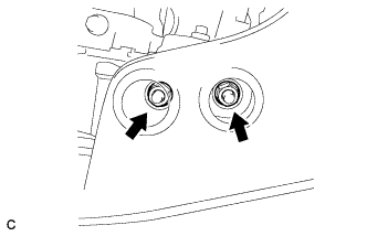
Remove the 2 hole plugs.
-
Remove the 3 nuts and front engine mounting insulator.
Tech Tips
Perform this procedure only when replacement of the front engine mounting insulator is necessary.
-
-
REMOVE ENGINE MOUNTING INSULATOR LH
-
Remove the 2 hole plugs.
-
Remove the 3 nuts and engine mounting insulator LH.
Tech Tips
Perform this procedure only when replacement of the engine mounting insulator LH is necessary.
-
-
REMOVE ENGINE MOUNTING INSULATOR RH
-
Remove the 2 hole plugs.
-
Remove the 3 nuts and engine mounting insulator RH.
Tech Tips
Perform this procedure only when replacement of the engine mounting insulator RH is necessary.
-
-
REMOVE REAR ENGINE MOUNTING INSULATOR ASSEMBLY
-
Remove the 2 hole plugs.
-
Remove the 2 nuts and rear engine mounting insulator assembly.
Note
Do not remove the rear engine mounting insulator assembly through bolts. Doing so makes it difficult to install the rear engine mounting insulator assembly.
Tech Tips
Perform this procedure only when replacement of the engine mounting insulator assembly is necessary.
-
-
REMOVE FRONT LOWER SUSPENSION ARM LH
-
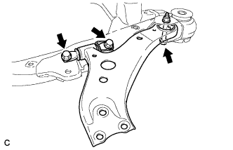
Remove the 3 bolts, nut and front lower suspension arm from the front frame assembly.
-
Remove the front lower arm bushing stopper from the front lower suspension arm.
-
-
REMOVE FRONT LOWER SUSPENSION ARM RH
Tech Tips
Perform the same procedure as the LH side.
-
REMOVE FRONT SUSPENSION MEMBER DYNAMIC DAMPER
-
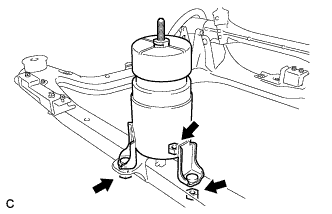
Remove the 2 bolts and front suspension member dynamic damper.
-
-
REMOVE FRONT SUSPENSION MEMBER DYNAMIC DAMPER (w/o Active Stabilizer System)
-
Remove the 2 bolts and front suspension member dynamic damper.
-
-
REMOVE FRONT SUSPENSION MEMBER DYNAMIC DAMPER (w/ Active Stabilizer System)
-
Remove the 2 bolts and front suspension member dynamic damper.
-
-
REMOVE FRONT SUSPENSION MEMBER BODY MOUNTING FRONT STOPPER
-
REMOVE FRONT SUSPENSION MEMBER BODY MOUNTING REAR STOPPER
-
REMOVE FRONT SUSPENSION MEMBER BODY MOUNTING FRONT CUSHION
-
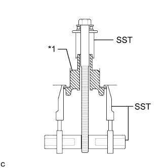
Text in Illustration *1 Front Suspension Member Body Mounting Front Cushion Install SST as shown in the illustration.
- SST
- 09830-10010 ( 09830-01010, 09830-01040, 09830-01050 )
- 09950-40011 ( 09951-04020, 09952-04010, 09954-04010, 09955-04011 )
-
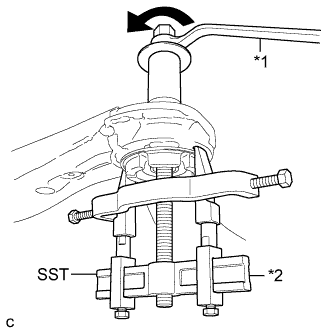
Text in Illustration *1 Turn *2 Hold Using SST, remove the front suspension member body mounting front cushion.
Note
-
Make sure that the claws of SST are securely hung onto the mounting cushion.
-
Tighten SST slowly and evenly.
-
Be careful as the mounting cushion may fly out.
-
The mounting cushion cannot be reused.
-
-
-
REMOVE FRONT SUSPENSION MEMBER BODY MOUNTING REAR CUSHION LH
-
Text in Illustration *1 Front Suspension Member Body Mounting Rear Cushion Install SST as shown in the illustration.
- SST
- 09830-10010 ( 09830-01010, 09830-01040, 09830-01050 )
- 09950-40011 ( 09951-04020, 09952-04010, 09954-04010, 09955-04011 )
-
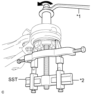
Text in Illustration *1 Turn *2 Hold Using SST, remove the front suspension member body mounting rear cushion LH.
Note
-
Make sure that the claws of SST are securely hung onto the mounting cushion.
-
Tighten SST slowly and evenly.
-
Be careful as the mounting cushion may fly out.
-
The mounting cushion cannot be reused.
-
-
-
REMOVE FRONT SUSPENSION MEMBER BODY MOUNTING REAR CUSHION RH
Tech Tips
Perform the same procedure as the LH side.