FRONT LOWER BALL JOINT INSTALLATION

Note
When the brake pedal is first depressed after replacing the brake pads or pushing back the disc brake piston, DTC C1341, C1342, C1343 and/or C1344 may be stored. As there is no malfunction, clear the DTC(s).
Tech Tips
-
Use the same procedure for the LH side and RH side.
-
The procedure listed below is for the LH side.
-
INSTALL FRONT LOWER BALL JOINT ASSEMBLY
-
Install the front lower ball joint to the steering knuckle with the nut (Type A or Type B).
- Torque:
- 123 N*m { 1254 kgf*cm, 91 ft.*lbf }
Note
Prevent oil from adhering to the screw and tapered parts.
-
When installing the nut (Type A):
-
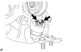
Install a new clip to the nut as shown in the illustration.
Note
-
If the holes for the clip are not aligned, tighten the nut further up to 60°.
-
Insert the clip forward of the vehicle.
-
-
-
When installing the nut (Type B):
-
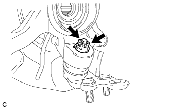
Install a new cotter pin to the nut as shown in the illustration.
Note
If the holes for the cotter pin are not aligned, tighten the nut further up to 60°.
-
-
-
INSTALL FRONT AXLE ASSEMBLY
-
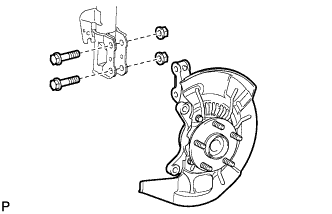
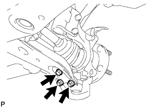
Install the front axle assembly to the front shock absorber with the 2 bolts and 2 nuts.
- Torque:
- 290 N*m { 2957 kgf*cm, 214 ft.*lbf }
Note
Keep the bolts from rotating when tightening the nuts.
-
-
INSTALL FRONT DRIVE SHAFT ASSEMBLY
-
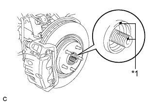
Text in Illustration *1 Matchmark Align the matchmarks and install the front drive shaft assembly to the front axle hub sub-assembly.
-
-
INSTALL FRONT LOWER SUSPENSION ARM
-
Install the front lower suspension arm to the front lower ball joint with the bolt and 2 nuts.
- Torque:
- 92 N*m { 938 kgf*cm, 68 ft.*lbf }
-
-
CONNECT TIE ROD ASSEMBLY
-
Connect the tie rod assembly LH to the steering knuckle with the nut.
- Torque:
- 49 N*m { 500 kgf*cm, 36 ft.*lbf }
-
Install a new cotter pin.
Note
Further tighten the nut up to 60° if the holes for the cotter pin are not aligned.
-
-
INSTALL FRONT DISC
-
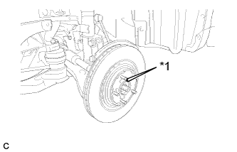
Text in Illustration *1 Matchmark Align the matchmarks and install the front disc.
Note
When replacing the disc with a new one, select the installation position where the front disc has minimal runout.
-
-
INSTALL FRONT DISC BRAKE CALIPER ASSEMBLY
-
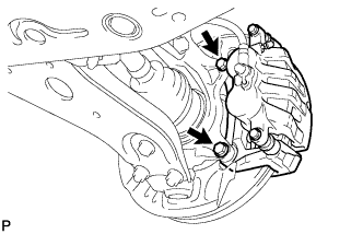
Install the front disc brake caliper assembly to the steering knuckle with the 2 bolts.
- Torque:
- 104 N*m { 1061 kgf*cm, 77 ft.*lbf }
-
-
INSTALL FRONT SPEED SENSOR
-
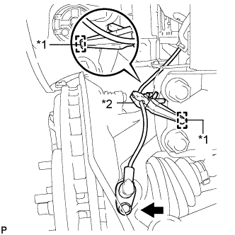
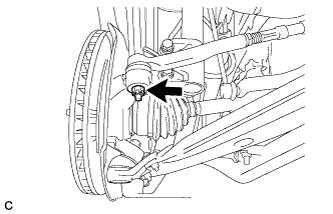
Text in Illustration *1 Hole *2 Resin Clamp Install the resin clamp and front speed sensor with the bolt.
- Torque:
- 8.0 N*m { 82 kgf*cm, 71 in.*lbf }
Note
-
Prevent foreign matter from attaching to the sensor tip.
-
Firmly insert the sensor body into the knuckle before tightening the bolt.
-
After installing the sensor to the knuckle, make sure that there is no clearance between the sensor stay and knuckle. Also make sure that no foreign matter is stuck between the parts.
-
To prevent interference between the sensor and magnetic rotor, do not rotate the sensor body during or after the insertion of the sensor body to the knuckle.
-
-
INSTALL FRONT AXLE SHAFT NUT
-
Clean the threaded parts on the drive shaft and a new axle shaft nut using a non-residue solvent.
Tech Tips
-
Be sure to perform this work for a new drive shaft.
-
Keep the threaded parts free of oil and foreign objects.
-
-
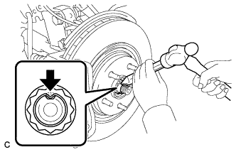
Using a socket wrench (30 mm), install the axle shaft nut.
- Torque:
- 294 N*m { 2998 kgf*cm, 217 ft.*lbf }
-
Using a chisel and hammer, stake the front axle shaft nut.
-
-
INSTALL FRONT WHEEL
- Torque:
- 103 N*m { 1050 kgf*cm, 76 ft.*lbf }
-
CHECK ABS SPEED SENSOR SIGNAL
Tech Tips
Check ABS speed sensor signal Click here.
-
INSPECT AND ADJUST FRONT WHEEL ALIGNMENT
Tech Tips
Inspect and adjust the front wheel alignment Click here.