SUSPENSION CONTROL ECU (for LHD) INSTALLATION

-
INSTALL SUSPENSION CONTROL ECU
-
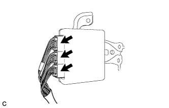
Connect the 3 connectors.
-
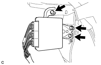
Install the suspension control ECU to the body with the 3 bolts.
- Torque:
- 8.5 N*m { 87 kgf*cm, 75 in.*lbf }
Note
-
Avoid any impact to the suspension control ECU.
-
Do not drop the ECU. If the ECU is dropped, replace it with a new one.
-
If the suspension control ECU is replaced with a new one, perform registration of vehicle identification information Click here.
-
-
INSTALL SKID CONTROL ECU ASSEMBLY
-
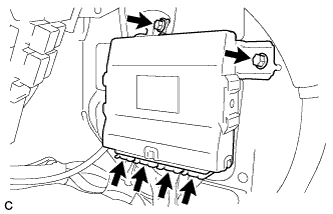
Connect the 4 connectors to the skid control ECU.
-
Install the skid control ECU with the 2 bolts.
- Torque:
- 8.5 N*m { 87 kgf*cm, 75 in.*lbf }
-
-
INSTALL ECU INTEGRATION BOX RH
-
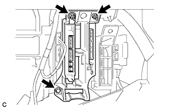
Install the ECU integration box RH with the 2 nuts and bolt.
-
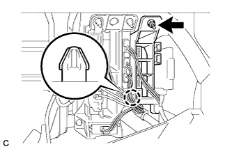
Install the No. 3 connector holder with the nut and claw.
-

Connect each connector.
-
-
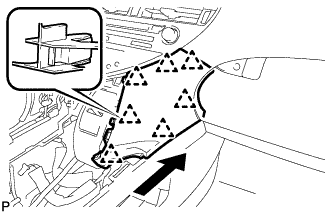
INSTALL GLOVE COMPARTMENT DOOR ASSEMBLY
-
Connect each connector.
-
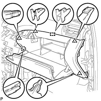
Engage the claw, 4 clips and guide.
-
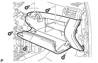
Install the glove compartment door assembly with the 5 screws <F>.
-
-
INSTALL FRONT PASSENGER SIDE KNEE AIRBAG ASSEMBLY
-
Check that the power switch is off.
-
Check that the cable is disconnected from the negative (-) battery terminal.
CAUTION:
Wait at least 90 seconds after disconnecting the cable from the negative (-) battery terminal to disable the SRS system.
-
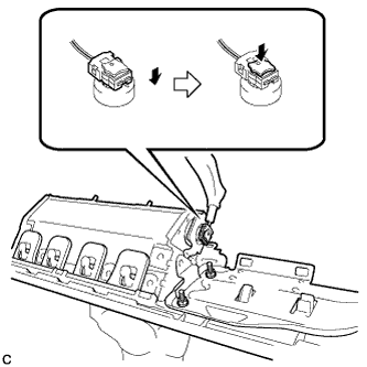
Connect the airbag connector to the front passenger side knee airbag assembly.
Note
When connecting any airbag connector, take care not to damage the airbag wire harness.
-
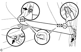
Temporarily install the front passenger side knee airbag assembly with the claw and 2 pins.
-
Install the front passenger side knee airbag assembly with the 3 bolts.
- Torque:
- 10 N*m { 102 kgf*cm, 7 ft.*lbf }
Note
Confirm that the front passenger side knee airbag assembly is installed securely without any excessive gaps and is not protruding outward.
-
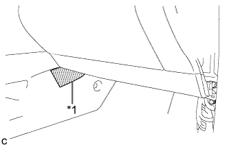
Text in Illustration *1 Protective Tape Remove the protective tape.
-
-
INSTALL INSTRUMENT PANEL GARNISH RH (w/o Airbag Cut Off Switch)
Tech Tips
Use the same procedure as for the LH side.
-
INSTALL INSTRUMENT PANEL GARNISH RH (w/ Airbag Cut Off Switch)
-
Connect the connector.
-
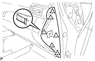
Engage the 6 clips to install the instrument panel garnish RH.
-
-
INSTALL NO. 2 INSTRUMENT PANEL UNDER COVER SUB-ASSEMBLY
-
Connect the connector.
-
Engage the 2 guides and 4 claw to install the No. 2 instrument panel under cover sub-assembly.
-
-
INSTALL COWL SIDE TRIM SUB-ASSEMBLY RH
Tech Tips
Use the same procedure as for the LH side Click here.
-
INSTALL FRONT DOOR SCUFF PLATE RH
Tech Tips
Use the same procedure as for the LH side Click here.
-
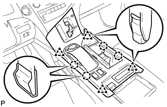
INSTALL LOWER INSTRUMENT PANEL FINISH PANEL
-
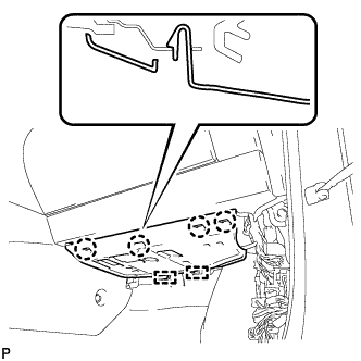
Engage the 7 clips to install the lower instrument panel finish panel as shown in the illustration.
-
-
INSTALL UPPER CONSOLE PANEL SUB-ASSEMBLY
-
Engage the clamp.
-
Connect each connector.
-
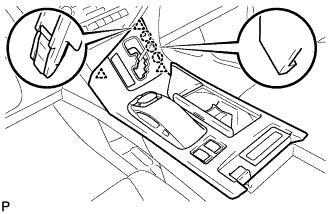
Engage the 3 claws and 3 clips.
-
w/o Seat Heater System:
-
Connect the connector to the console box hole cover.
-
-
w/ Seat Heater System:
-
Connect the connector.
-
Engage the 4 claws to install the seat heater switch assembly.
-
-
Engage the 4 claws and 4 clips to install the upper console panel sub-assembly.
-
-
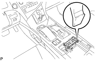
INSTALL SHIFT LEVER KNOB SUB-ASSEMBLY
-
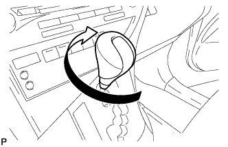
Turn the shift lever knob sub-assembly clockwise to install the shift lever knob sub-assembly.
-
-
CONNECT CABLE TO NEGATIVE BATTERY TERMINAL
Note
When disconnecting the cable, some systems need to be initialized after the cable is reconnected Click here.
-
INSTALL REAR DECK FLOOR BOX
-

Install the rear deck floor box with the 3 clips.
-
-
INSPECT SUSPENSION CONTROL SYSTEM
Note
If the suspension control ECU is replaced with a new one, perform registration of vehicle identification information.
-
Inspect the suspension control system Click here.
-
-
ADJUST VEHICLE HEIGHT
Note
If the suspension control ECU has been replaced, be sure to adjust the vehicle height.
-
Adjust the vehicle height Click here.
-
-
PERFORM INITIALIZATION
-
Perform initialization Click here.
-
-
CHECK SRS WARNING LIGHT
-
Check the SRS warning light Click here.
-
-
ADJUST HEADLIGHT ASSEMBLY (for HID Headlight)
-
Adjust the headlight Click here.
-
-
ADJUST HEADLIGHT ASSEMBLY (for LED Headlight)
-
Adjust the headlight Click here.
-