ACTIVE STABILIZER SUSPENSION SYSTEM, Diagnostic DTC:C194A, C194B, C194C

| DTC Code | DTC Name |
|---|---|
| C194A | Open in Front Motor Driver Circuit |
| C194B | Short to GND in Front Motor Driver |
| C194C | Short in Front Motor Driver Circuit |
DESCRIPTION
When an open or short is detected in the motor circuit of the front active stabilizer control ECU and front active stabilizer control actuator assembly, DTC C194A, C194B and/or C194C are output.
| DTC No. | DTC Detection Condition | Trouble Area |
|---|---|---|
| C194A | Open in motor driver detected |
|
| C194B | Short in motor driver ground detected | |
| C194C | Short in motor driver line detected |
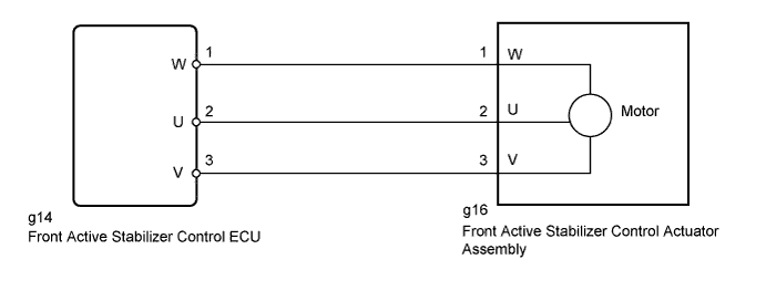
WIRING DIAGRAM
INSPECTION PROCEDURE
PROCEDURE
-
CHECK CONNECTOR CONNECTION CONDITION
-
Turn the power switch off.
-
Check that the wire harness connectors between the front active stabilizer control ECU and front active stabilizer control actuator assembly are not loose or disconnected and that the wire harness is not damaged.
OK Connectors are not loose or disconnected. Wire harness is not damaged. Tech Tips
If the wire harness of the front active stabilizer control actuator assembly is damaged, replace the front active stabilizer control actuator assembly Click here.
NG 
REPAIR OR REPLACE HARNESS OR CONNECTOR
OK 
-
-
CHECK HARNESS AND CONNECTOR (FRONT ACTIVE STABILIZER CONTROL ECU - FRONT ACTIVE STABILIZER CONTROL ACTUATOR ASSEMBLY)
-
Turn the power switch off.
-
Disconnect the g14 ECU connector.
-
Disconnect the g16 actuator connector.
-
Measure the resistance according to the value(s) in the table below.
Standard Resistance Tester Connection Condition Specified Condition g14-1 (W) - g16-1 (W) Always Below 1 Ω g14-1 (W) - Body ground Always 10 kΩ or higher g14-2 (U) - g16-2 (U) Always Below 1 Ω g14-2 (U) - Body ground Always 10 kΩ or higher g14-3 (V) - g16-3 (V) Always Below 1 Ω g14-3 (V) - Body ground Always 10 kΩ or higher
NG
REPAIR OR REPLACE HARNESS OR CONNECTOR
OK
-
-
INTERCHANGE FRONT AND REAR ACTIVE STABILIZER CONTROL ECU
-
Turn the power switch off.
-
Interchange the front active stabilizer control ECU with the rear active stabilizer control ECU, and install them securely Click here.
NEXT
-
-
CLEAR DTC
-
Turn the power switch off.
-
Connect the intelligent tester to the DLC3.
-
Turn the power switch on (IG) and the intelligent tester on.
-
Clear the DTCs Click here.
NEXT
-
-
CHECK OPERATION OF FRONT ACTIVE STABILIZER CONTROL ECU
-
Turn the power switch off.
-
Connect the intelligent tester to the DLC3.
-
Turn the power switch on (READY) and wait 30 seconds or more. Then check for rear active stabilizer DTCs Click here.
OK DTC C1922, C1923 and/or C1924 are not output Tech Tips
Interchange the front and rear active stabilizer control ECUs and check for DTCs. After interchanging the ECUs, if a rear active stabilizer DTC is stored, it can be determined that the front active stabilizer control ECU is malfunctioning. If no DTC is stored, the front active stabilizer control actuator assembly is malfunctioning.
NG
REPLACE ACTIVE STABILIZER CONTROL ECU ASSEMBLY Click here
OK 
REPLACE FRONT ACTIVE STABILIZER CONTROL ACTUATOR ASSEMBLY Click here
-