AIR SUSPENSION SYSTEM, Diagnostic DTC:C1782

| DTC Code | DTC Name |
|---|---|
| C1782 | Power Source Voltage Malfunction |
DESCRIPTION
| DTC No. | DTC Detection Condition | Trouble Area |
|---|---|---|
| C1782 | When one of the following conditions is met:
|
|
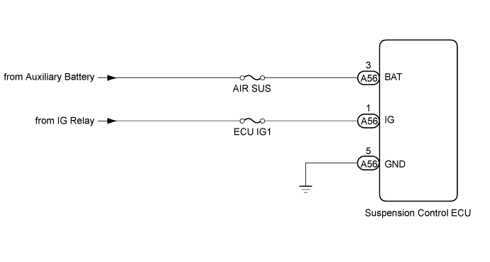
WIRING DIAGRAM
INSPECTION PROCEDURE
Note
-
Before performing troubleshooting, inspect the connectors of related circuits.
-
Before replacing the suspension control ECU, perform all of the following again: 1) symptom simulation Click here; 2) DTC inspection Click here; and 3) Intelligent tester inspection (Data List or Active Test) Click here. If no malfunctions are found in other areas, replace the suspension control ECU.
-
If the suspension control ECU is replaced, the vehicle height offset calibration and registration of vehicle identification information must be performed Click here and Click here
Tech Tips
Inspect the fuses for circuits related to this system before performing the following inspection procedure.
PROCEDURE
-
READ VALUE USING INTELLIGENT TESTER (IG AND +B POWER SOURCE VOLTAGE)
-
Turn the power switch off.
-
Connect the intelligent tester to the DLC3.
-
Turn the power switch on (IG) and the intelligent tester on.
-
Enter the following menus: Chassis / Air suspension / Data List.
-
According to the display on the intelligent tester.
Air suspension system Tester Display Measurement Item/Range Normal Condition Diagnostic Note IG Power Source Voltage ECU power supply voltage /
min.: 0 V
max.: 255 V
Actual ECU power supply voltage: 11 to 14 V - +B Power Source Voltage ECU power supply voltage /
min.: 0 V
max.: 255 V
Actual ECU power supply voltage: 11 to 14 V - OK 11 to 14 V Result Result Proceed to NG A OK B
B 
CHECK DTC Click here
A 
-
-
CHECK AUXILIARY BATTERY
-
Measure the auxiliary battery voltage.
Standard voltage Tester Connection Condition Specified Condition Auxiliary battery terminal Always 11 to 14 V
NG 
GO TO CHARGING SYSTEM Click here
OK
-
-
CHECK HARNESS AND CONNECTOR (POWER SOURCE OF ECU)
-
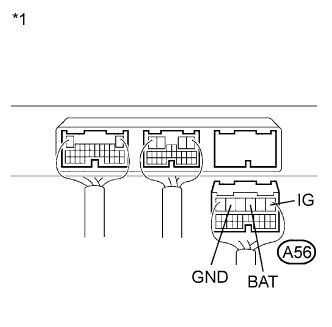
Text in Illustration *1 Rear view of wire harness connector
(to Suspension Control ECU)
Disconnect the A56 ECU connector.
-
Measure the voltage according to the value(s) in the table below.
Standard voltage Tester Connection Condition Specified Condition A56-3 (BAT) - Body ground Always 11 to 14 V A56-1 (IG) - Body ground Power switch on (IG) 11 to 14 V -
Measure the resistance according to the value(s) in the table below.
Standard resistance Tester Connection Condition Specified Condition A56-5 (GND) - Body ground Always Below 1 Ω
NG
REPAIR OR REPLACE HARNESS OR CONNECTOR
OK
-
-
CHECK DTC
-
Clear the DTC Click here.
-
Check for DTC Click here.
Result Condition Proceed to DTC is output (for LHD) A DTC is output (for RHD) B DTC is not output C
B
REPLACE SUSPENSION CONTROL ECU (for RHD) Click here
C
USE SIMULATION METHOD TO CHECK Click here
A 
REPLACE SUSPENSION CONTROL ECU (for LHD) Click here
-