AIR SUSPENSION SYSTEM, Diagnostic DTC:C1752

| DTC Code | DTC Name |
|---|---|
| C1752 | Height Control Compressor Motor Circuit Malfunction |
DESCRIPTION
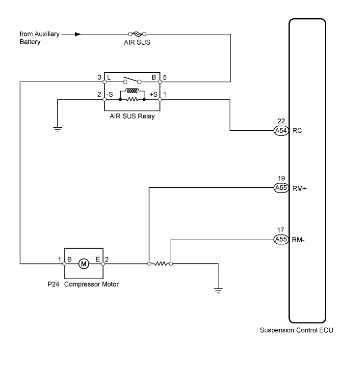
The signal from the suspension control ECU turns on the AIR SUS relay. At that time, auxiliary battery voltage is input to the height control compressor motor through the AIR SUS relay. The height control compressor motor starts.
| DTC No. | DTC Detection Condition | Trouble Area |
|---|---|---|
| C1752 | With the AIR SUS relay activated, a lock signal of the height control compressor motor is detected for 4 sec. or more. |
|
WIRING DIAGRAM
INSPECTION PROCEDURE
Note
-
Before performing troubleshooting, inspect the connectors of related circuits.
-
If DTC C1782 (Power Source Voltage Malfunction) is output at the same time, perform troubleshooting for C1782 first Click here.
-
Before replacing the suspension control ECU, perform all of the following again: 1) symptom simulation Click here; 2) DTC inspection Click here; and 3) Intelligent tester inspection (Data List or Active Test) Click here. If no malfunctions are found in other areas, replace the suspension control ECU.
-
If the suspension control ECU is replaced, the vehicle height offset calibration and registration of vehicle identification information must be performed Click here and Click here
Tech Tips
Inspect the fuses for circuits related to this system before performing the following inspection procedure.
PROCEDURE
-
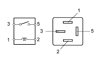
INSPECT AIR SUS RELAY
-
Turn the power switch off.
-
Remove the AIR SUS relay from the engine room J/B.
-
Measure the resistance according to the value(s) in the table below.
Standard resistance Tester Connection Condition Specified Condition 3 - 5 When battery voltage is not applied between terminals 1 and 2 10 kΩ or higher When battery voltage is applied between terminals 1 and 2 Below 1 Ω
NG 
REPLACE AIR SUS RELAY
OK 
-
-
INSPECT HEIGHT CONTROL COMPRESSOR ASSEMBLY (COMPRESSOR MOTOR)
-
Disconnect the compressor motor connector.
-
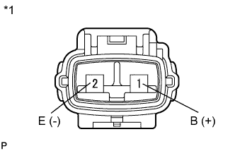
Text in Illustration *1 Component without harness connected
(Compressor Motor)
Connect a positive (+) lead from the battery to terminal 1 (B) and a negative (-) lead to terminal 2 (E).
-
Check the operation of the compressor motor.
OK Motor operates Note
-
Do not operate the height control compressor for 60 seconds or more.
-
Stop applying voltage immediately if the compressor stops operating because a short will occur and the compressor motor will lock up, causing the flow of excessive current.
-
NG
REPLACE HEIGHT CONTROL COMPRESSOR ASSEMBLY Click here
OK
-
-
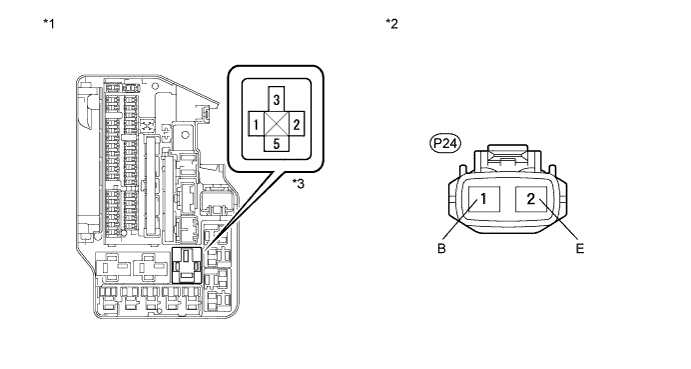
CHECK HARNESS AND CONNECTOR (POWER SOURCE OF COMPRESSOR MOTOR)
-
Remove the AIR SUS relay from the engine room J/B.
-
Measure the voltage according to the value(s) in the table below.
Standard voltage Tester Connection Condition Specified Condition J/B AIR SUS relay terminal 5 - Body ground Always 11 to 14 V Text in Illustration *1 Component without relay
(Engine Room J/B)
*2 Front view of wire harness connector
(to Compressor Motor)
*3 AIR SUS relay - - -
Disconnect the P24 compressor connector.
-
Measure the resistance according to the value(s) in the table below.
Standard resistance Tester Connection Condition Specified Condition J/B AIR SUS relay terminal 3 - P24-1 (B) Always Below 1 Ω P24-1 (B) - Body ground Always 10 kΩ or higher P24-2 (E) - Body ground Always Below 1 Ω
NG
REPAIR OR REPLACE HARNESS OR CONNECTOR
OK
-
-
CHECK HARNESS AND CONNECTOR (COMPRESSOR MOTOR LOCK DETECTION CIRCUIT)
-
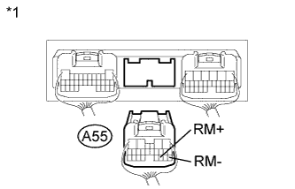
Text in Illustration *1 Rear view of wire harness connector
(to Suspension Control ECU)
Disconnect the A55 ECU connector.
-
Measure the resistance according to the value(s) in the table below.
Standard resistance Tester Connection Condition Specified Condition A55-19 (RM+) - A55-17 (RM-) Always 6.4 to 7.4 mΩ Result Condition Proceed to OK (for LHD) A OK (for RHD) B NG C
B
REPLACE SUSPENSION CONTROL ECU (for RHD) Click here
C
REPAIR OR REPLACE HARNESS OR CONNECTOR
A 
REPLACE SUSPENSION CONTROL ECU (for LHD) Click here
-