AIR SUSPENSION SYSTEM, Diagnostic DTC:C1751

| DTC Code | DTC Name |
|---|---|
| C1751 | Compressor Relay Coil Malfunction |
DESCRIPTION
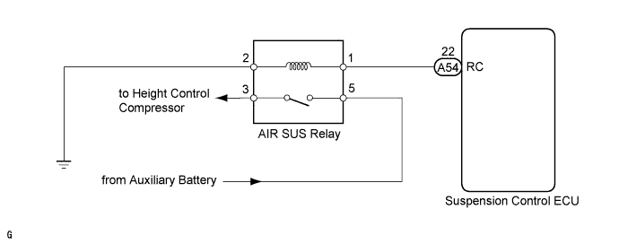
The signal from the suspension control ECU turns on the AIR SUS relay, and then the height control compressor motor starts.
| DTC No. | DTC Detection Condition | Trouble Area |
|---|---|---|
| C1751 | When either of the following is detected:
|
|
WIRING DIAGRAM
INSPECTION PROCEDURE
Note
-
Before performing troubleshooting, inspect the connectors of related circuits.
-
If DTC C1782 (Power Source Voltage Malfunction) is output at the same time, perform troubleshooting for C1782 first Click here.
-
Before replacing the suspension control ECU, perform all of the following again: 1) symptom simulation Click here; 2) DTC inspection Click here; and 3) Intelligent tester inspection (Data List or Active Test) Click here. If no malfunctions are found in other areas, replace the suspension control ECU.
-
If the suspension control ECU is replaced, the vehicle height offset calibration and registration of vehicle identification information must be performed Click here and Click here
PROCEDURE
-
INSPECT AIR SUS RELAY
-
Turn the power switch off.
-
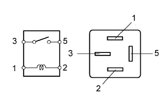
Remove the AIR SUS relay from the engine room J/B.
-
Measure the resistance according to the value(s) in the table below.
Standard resistance Tester Connection Condition Specified Condition 3 - 5 When battery voltage is not applied between terminals 1 and 2 10 kΩ or higher When battery voltage is applied between terminals 1 and 2 Below 1 Ω
NG 
REPLACE AIR SUS RELAY
OK 
-
-
CHECK HARNESS AND CONNECTOR (AIR SUS RELAY - ECU AND BODY GROUND)
-
Disconnect the A54 ECU connector.
-
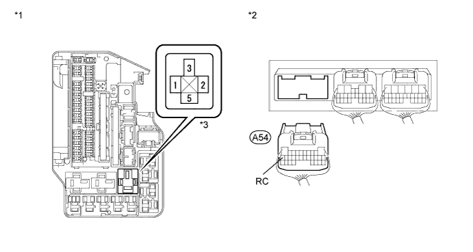
Remove the AIR SUS relay from the engine room J/B.
-
Measure the resistance according to the value(s) in the table below.
Standard resistance Tester Connection Condition Specified Condition A54-22 (RC) - J/B AIR SUS relay terminal 1 Always Below 1 Ω A54-22 (RC) - Body ground Always 10 kΩ or higher J/B AIR SUS relay terminal 2- Body ground Always Below 1 Ω Text in Illustration *1 Component without relay
(Engine Room J/B)
*2 Rear view of wire harness connector
(to Suspension Control ECU)
*3 AIR SUS relay - - Result Condition Proceed to OK (for LHD) A OK (for RHD) B NG C
B
REPLACE SUSPENSION CONTROL ECU (for RHD) Click here
C
REPAIR OR REPLACE HARNESS OR CONNECTOR
A 
REPLACE SUSPENSION CONTROL ECU (for LHD) Click here
-