AIR SUSPENSION SYSTEM, Diagnostic DTC:C1792

| DTC Code | DTC Name |
|---|---|
| C1792 | Height Control Switch Circuit (Test Mode DTC) |
DESCRIPTION
Pressing the height control switch (driver seat) while the power switch on (READY) for approximately 1 second switches modes. If the switch is pressed while the vehicle height is changing, vehicle height control will be cancelled.
| DTC No. | DTC Detecting Condition | Trouble Area |
|---|---|---|
| C1792 | Detected only during Test Mode. |
|
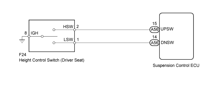
WIRING DIAGRAM
INSPECTION PROCEDURE
Note
-
Before performing troubleshooting, inspect the connectors of related circuits.
-
Before replacing the suspension control ECU, perform all of the following again: 1) symptom simulation Click here; 2) DTC inspection Click here; and 3) Intelligent tester inspection (Data List or Active Test) Click here. If no malfunctions are found in other areas, replace the suspension control ECU.
-
If the suspension control ECU is replaced, the vehicle height offset calibration and registration of vehicle identification information must be performed Click here and Click here
PROCEDURE
-
INSPECT HEIGHT CONTROL SWITCH (DRIVER SEAT)
-
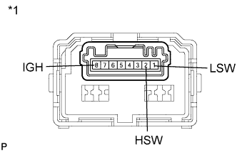
Text in Illustration *1 Component without harness connected
(Height Control Switch)
Disconnect the height control switch (driver seat) connector.
-
Measure the resistance according to the values in the table below.
Standard resistance Tester Connection Condition Specified Condition 1 (LSW) - 8 (IGH) Height control switch while pressing "UP" button 10 kΩ or higher Height control switch while pressing "DOWN" button Below 1 Ω Neutral position 10 kΩ or higher 2 (HSW) - 8 (IGH) Height control switch while pressing "UP" button Below 1 Ω Height control switch while pressing "DOWN" button 10 kΩ or higher Neutral position 10 kΩ or higher
NG 
REPLACE HEIGHT CONTROL SWITCH (DRIVER SEAT) Click here
OK 
-
-
CHECK HARNESS AND CONNECTOR (HEIGHT CONTROL SWITCH - ECU AND BODY GROUND)
-
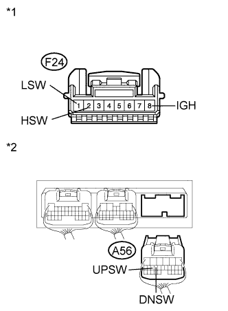
Text in Illustration *1 Front view of wire harness connector
(to Height Control Switch)
*2 Rear view of wire harness connector
(to Suspension Control ECU)
Disconnect the A56 ECU connector.
-
Disconnect the F24 height control switch (driver seat) connector.
-
Measure the resistance according to the values in the table below.
Standard resistance Tester Connection Condition Specified Condition F24-1 (LSW) - A56-14 (DNSW) Always Below 1 Ω F24-2 (HSW) - A56-15 (UPSW) Always Below 1 Ω A56-14 (DNSW) - Body ground Always 10 kΩ or higher A56-15 (UPSW) - Body ground Always 10 kΩ or higher Result Condition Proceed to OK (for LHD) A OK (for RHD) B NG C
B
REPLACE SUSPENSION CONTROL ECU (for RHD) Click here
C
REPAIR OR REPLACE HARNESS OR CONNECTOR
A 
REPLACE SUSPENSION CONTROL ECU (for LHD) Click here
-