REAR AXLE HUB INSTALLATION

Tech Tips
-
Use the same procedure for the RH side and LH side.
-
The procedure listed below is for the LH side.
-
INSTALL REAR AXLE HUB AND BEARING ASSEMBLY (for 2WD)
-

Install the rear axle hub and bearing assembly to the rear axle carrier sub-assembly with the 4 bolts.
- Torque:
- 125 N*m { 1275 kgf*cm, 92 ft.*lbf }
-
-
INSTALL REAR AXLE HUB AND BEARING ASSEMBLY (for AWD)
-
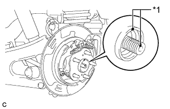
Text in Illustration *1 Matchmark Align the matchmarks on the rear drive shaft assembly and rear axle hub and bearing assembly, and then insert the rear drive shaft assembly to the rear axle hub and bearing assembly.
-
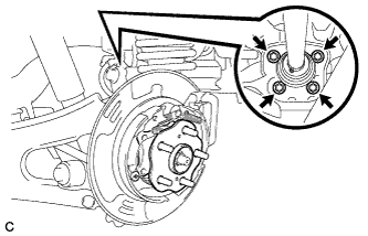
Install the rear axle hub and bearing assembly to the rear axle carrier sub-assembly with the 4 bolts.
- Torque:
- 125 N*m { 1275 kgf*cm, 92 ft.*lbf }
-
-
INSTALL REAR AXLE SHAFT NUT (for AWD)
-
Clean the threaded parts on the rear drive shaft assembly and a new rear axle shaft nut using a non-residue solvent.
Note
-
Be sure to perform this work for a new rear drive shaft assembly.
-
Keep the threaded parts free of oil and foreign matter.
-
-
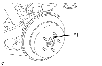
Temporarily install the rear disc with the 5 hub nuts.
-
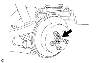
While applying the parking brakes, temporarily install the new rear axle shaft nut.
- Torque:
- 294 N*m { 2998 kgf*cm, 217 ft.*lbf }
Note
Stake the rear axle shaft nut after inspecting for looseness and runout in the following steps.
-
Remove the 5 hub nuts and the rear disc.
-
-
INSPECT REAR AXLE HUB BEARING LOOSENESS
-
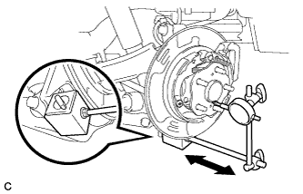
Using a dial indicator, check for looseness near the center of the rear axle hub.
Maximum looseness 0 mm (0 in.) Note
-
Ensure that the dial indicator is set perpendicular to the measurement surface.
-
Keep the magnet of the dial indicator away from the rear axle hub and bearing assembly.
Tech Tips
If the looseness exceeds the maximum, replace the rear axle hub and bearing assembly.
-
-
-
INSPECT REAR AXLE HUB RUNOUT
-
Using a dial indicator, check for runout on the surface of the rear axle hub outside the rear axle hub bolt.
Maximum runout 0.08 mm (0.00314 in.) Note
-
Ensure that the dial indicator is set perpendicular to the measurement surface.
-
Keep the magnet of the dial indicator away from the rear axle hub and bearing assembly.
Tech Tips
If the runout exceeds the maximum, replace the rear axle hub and bearing assembly.
-
-
-
INSTALL REAR SPEED SENSOR WIRE (for 2WD)
-
Connect the connector to the rear speed sensor.
-
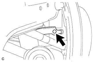
Install the No. 1 bracket with the bolt.
- Torque:
- 8.0 N*m { 82 kgf*cm, 71 in.*lbf }
-
-
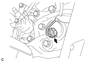
INSTALL REAR SPEED SENSOR (for AWD)
-
Install the rear speed sensor to the rear axle carrier sub-assembly with the bolt.
- Torque:
- 8.5 N*m { 87 kgf*cm, 75 in.*lbf }
Note
-
Prevent foreign matter from attaching to the sensor tip.
-
Do not file the rear speed sensor installation hole or surface because the gap between the magnet rotor and rear speed sensor is important.
-
Do not twist or apply excessive force to the front speed sensor during installation to prevent it from being damaged.
-
Install the rear speed sensor without twisting it.
-
-
INSTALL REAR DISC
-
Text in Illustration *1 Matchmark Align the matchmarks and install the rear disc.
Note
When replacing the rear disc with a new one, select the installation position where the rear disc has minimal runout.
-
-
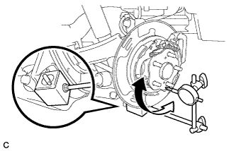
INSTALL PARKING BRAKE SHOE ADJUSTING HOLE PLUG
-
Install the parking brake shoe adjusting hole plug.
-
-
INSTALL REAR DISC BRAKE CALIPER ASSEMBLY
-
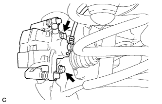
Install the rear disc brake caliper assembly with the 2 bolts.
- Torque:
- 78 N*m { 799 kgf*cm, 58 ft.*lbf }
-
-
STAKE REAR AXLE SHAFT NUT (for AWD)
-
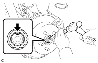
Using a chisel and a hammer, stake the rear axle shaft nut.
-
-
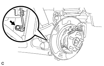
INSTALL REAR SUSPENSION ARM COVER (w/o Air Suspension)
-
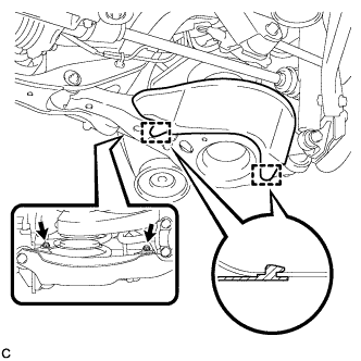
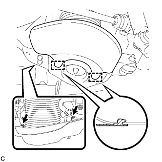
Insert the 2 guides of the rear suspension arm cover to the rear No. 2 suspension arm assembly.
-
Install the rear suspension arm cover to the rear No. 2 suspension arm assembly with the 2 bolts as shown in the illustration.
- Torque:
- 12 N*m { 122 kgf*cm, 9 ft.*lbf }
Note
Make sure that the 2 guides of rear suspension arm cover are inserted.
-
-
INSTALL REAR SUSPENSION ARM COVER (w/ Air Suspension)
-
Insert the 2 guides of the rear suspension arm cover to the rear No. 2 suspension arm assembly.
-
Install the rear suspension arm cover to the rear No. 2 suspension arm assembly with the 2 bolts as shown in the illustration.
- Torque:
- 12 N*m { 122 kgf*cm, 9 ft.*lbf }
Note
Make sure that the 2 guides of rear suspension arm cover are inserted.
-
Check that the rear pneumatic cylinder cover is not deformed or collapsed inward.
-
-
ADJUST PARKING BRAKE SHOE CLEARANCE AND PARKING BRAKE PEDAL TRAVEL (for LHD)
-
Remove the No. 1 instrument panel under cover sub-assembly Click here.
-
Completely release the parking brake pedal.
-
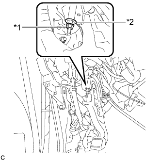
Text in Illustration *1 Lock Nut *2 Adjusting Nut Loosen the lock nut and the adjusting nut to completely release the parking brake cable.
-
Remove the rear wheels.
-
Temporarily install the hub nuts to the hub bolts.
Tech Tips
Securely install the hub nuts to the rear disc.
-
Remove the parking brake shoe adjusting hole plug.
-
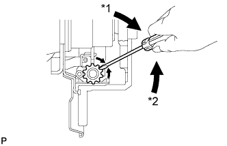
Text in Illustration *1 Expand *2 Contract Turn the shoe adjuster and expand the shoe until the disc locks.
-
Turn and contract the shoe adjuster until the disc can rotate smoothly.
Standard Returns 8 notches. -
Check that there is no brake drag against the shoe.
-
Install the parking brake shoe adjusting hole plug.
-
Turn the adjusting nut until the parking brake pedal travel is corrected to be within the specified range.
Parking brake pedal travel 7 to 10 notches at 300 N (31 kgf, 67.5 lbf) -
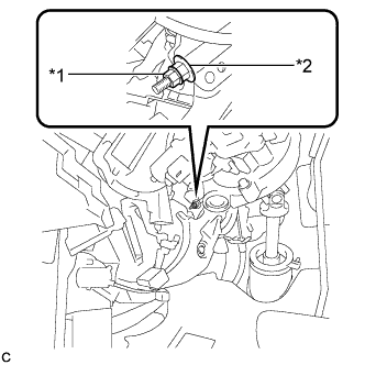
Text in Illustration *1 Lock Nut *2 Adjusting Nut Using a wrench or an equivalent tool, hold the adjusting nut and tighten the lock nut.
- Torque:
- 7.0 N*m { 71 kgf*cm, 62 in.*lbf }
-
Operate the parking brake pedal 3 to 4 times, and check the parking brake pedal travel.
-
Check that there is no brake drag against the shoe.
-
Remove the hub nuts from the hub bolts.
-
Install the rear wheels.
- Torque:
- 103 N*m { 1050 kgf*cm, 76 ft.*lbf }
-
Install the No. 1 instrument panel under cover sub-assembly Click here.
-
-
ADJUST PARKING BRAKE SHOE CLEARANCE AND PARKING BRAKE PEDAL TRAVEL (for RHD)
-
Remove the No. 1 instrument panel under cover sub-assembly Click here.
-
Completely release the parking brake pedal.
-
Text in Illustration *1 Lock Nut *2 Adjusting Nut Loosen the lock nut and the adjusting nut to completely release the parking brake cable.
-
Remove the rear wheels.
-
Temporarily install the hub nuts to the hub bolts.
Tech Tips
Securely install the hub nuts to the rear disc.
-
Remove the shoe adjusting hole plug.
-
Text in Illustration *1 Expand *2 Contract Turn the shoe adjuster and expand the shoe until the disc locks.
-
Turn and contract the shoe adjuster until the disc can rotate smoothly.
Standard Returns 8 notches. -
Check that there is no brake drag against the shoe.
-
Install the shoe adjusting hole plug.
-
Turn the adjusting nut until the parking brake pedal travel is corrected to be within the specified range.
Parking brake pedal travel 7 to 10 notches at 300 N (31 kgf, 67.5 lbf) -
Text in Illustration *1 Lock Nut *2 Adjusting Nut Using a wrench or an equivalent tool, hold the adjusting nut and tighten the lock nut.
- Torque:
- 7.0 N*m { 71 kgf*cm, 62 in.*lbf }
-
Operate the parking brake pedal 3 to 4 times, and check the parking brake pedal travel.
-
Check that there is no brake drag against the shoe.
-
Remove the hub nuts from the hub bolts.
-
Install the rear wheels.
- Torque:
- 103 N*m { 1050 kgf*cm, 76 ft.*lbf }
-
Install the No. 1 instrument panel under cover sub-assembly Click here.
-
-
INSTALL REAR WHEEL
- Torque:
- 103 N*m { 1050 kgf*cm, 76 ft.*lbf }
-
CHECK FOR SPEED SENSOR SIGNAL