FRONT AXLE HUB INSTALLATION

Tech Tips
-
Use the same procedure for the RH side and LH side.
-
The procedure listed below is for the LH side.
-
INSTALL FRONT AXLE HUB BEARING
-
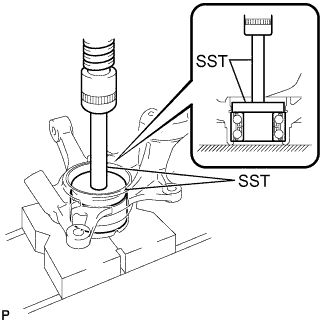
Using SST and a press, install a new front axle hub bearing to the steering knuckle.
- SST
- 09950-60020 ( 09951-00810 )
- 09950-70010 ( 09951-07100 )
-
-
INSTALL FRONT DISC BRAKE DUST COVER
-
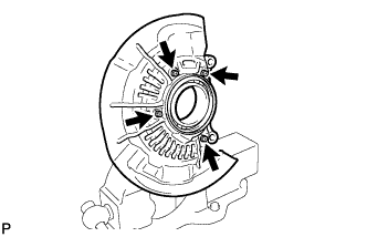
Install the front disc brake dust cover to the steering knuckle with the 4 bolts.
- Torque:
- 8.3 N*m { 85 kgf*cm, 73 in.*lbf }
-
-
INSTALL FRONT AXLE HUB SUB-ASSEMBLY
-
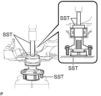
Using SST and a press, install the front axle hub sub-assembly to the steering knuckle.
- SST
- 09608-32010
- 09950-60010 ( 09951-00610 )
- 09950-70010 ( 09951-07100 )
-
-
INSTALL FRONT AXLE HUB HOLE SNAP RING
-

Using snap ring pliers, install a new front axle hub hole snap ring.
-
-
INSTALL FRONT NO. 1 WHEEL BEARING DUST DEFLECTOR
-
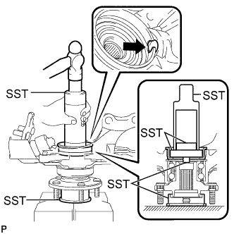
Using SST and a hammer, install a new front No. 1 wheel bearing dust deflector.
- SST
- 09316-60011 ( 09316-00011 )
- 09608-32010
- 09950-60010 ( 09951-00500, 09952-06010 )
- 09950-60020 ( 09951-00810 )
Tech Tips
Align the cutout for the speed sensor in the front No. 1 wheel bearing dust deflector with the hole of the steering knuckle.
-
-
INSTALL FRONT AXLE ASSEMBLY
-
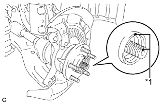
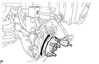
Text in Illustration *1 Matchmark Align the matchmarks and install the front drive shaft assembly to the front axle hub sub-assembly.
-
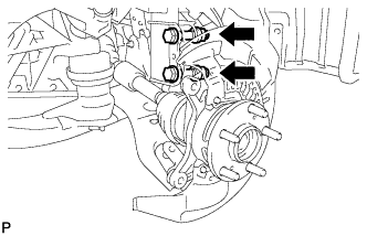
Install the front axle assembly to the front shock absorber with the 2 bolts and 2 nuts.
- Torque:
- 290 N*m { 2957 kgf*cm, 214 ft.*lbf }
Note
When installing the nuts, keep the bolts from rotating.
-
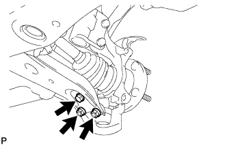
Install the front lower No. 1 suspension arm sub-assembly to the front lower ball joint assembly with the bolt and 2 nuts.
- Torque:
- 92 N*m { 938 kgf*cm, 68 ft.*lbf }
-
-
CONNECT TIE ROD ASSEMBLY
-
Connect the tie rod assembly LH to the steering knuckle with the nut.
- Torque:
- 49 N*m { 500 kgf*cm, 36 ft.*lbf }
-
Install a new cotter pin.
Note
Further tighten the nut up to 60° if the holes for the cotter pin are not aligned.
-
-
INSTALL FRONT DISC
-
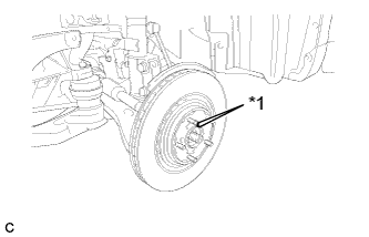
Text in Illustration *1 Matchmark Align the matchmarks and install the front disc.
Note
When replacing the disc with a new one, select the installation position where the front disc has minimal runout.
-
-
INSTALL FRONT DISC BRAKE CALIPER ASSEMBLY
-
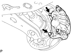
Install the front disc brake caliper assembly to the steering knuckle with the 2 bolts.
- Torque:
- 104 N*m { 1061 kgf*cm, 77 ft.*lbf }
-
-
INSTALL FRONT AXLE SHAFT NUT
-
Clean the threaded parts on the front drive shaft assembly and front axle shaft nut using a non-residue solvent.
Note
-
Be sure to perform this work for a new front drive shaft assembly.
-
Keep the threaded parts free of oil and foreign matter.
-
-
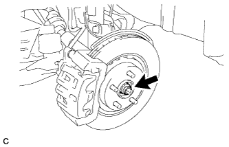
Using a socket wrench (30 mm), install a new front axle hub shaft nut.
- Torque:
- 294 N*m { 2998 kgf*cm, 217 ft.*lbf }
Note
Stake the nut after inspecting for looseness and runout in the following steps.
Tech Tips
Keep depressing the brake pedal to prevent the front drive shaft from rotating.
-
-
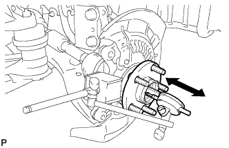
SEPARATE FRONT DISC BRAKE CALIPER ASSEMBLY
-
Remove the 2 bolts and separate the front disc brake caliper assembly.
Note
Use wire or an equivalent tool to keep the brake caliper from hanging down by the flexible hose.
-
-
REMOVE FRONT DISC
-
Text in Illustration *1 Matchmark Remove the front disc.
Tech Tips
Put matchmarks on the disc and the axle hub.
-
-
INSPECT FRONT AXLE HUB BEARING LOOSENESS
-
Using a dial indicator, check for looseness near the center of the front axle hub.
Maximum looseness 0 mm (0 in.) Note
-
Ensure that the dial indicator is set perpendicular to the measurement surface.
-
Keep the magnet of the dial indicator away from the front speed sensor.
Tech Tips
If the looseness exceeds the maximum, replace the front axle hub bearing.
-
-
-
INSPECT FRONT AXLE HUB RUNOUT
-
Using a dial indicator, check for runout on the surface of the axle hub outside the hub bolt.
Maximum runout 0.05 mm (0.0020 in.) Note
-
Ensure that the dial indicator is set perpendicular to the measurement surface.
-
Keep the magnet of the dial indicator away from the front speed sensor.
Tech Tips
If the runout exceeds the maximum, replace the front axle hub.
-
-
-
INSTALL FRONT DISC
-
Text in Illustration *1 Matchmark Align the matchmarks and install the front disc.
Note
When replacing the disc with a new one, select the installation position where the front disc has minimal runout.
-
-
INSTALL FRONT DISC BRAKE CALIPER ASSEMBLY
-
Install the front disc brake caliper assembly to the steering knuckle with the 2 bolts.
- Torque:
- 104 N*m { 1061 kgf*cm, 77 ft.*lbf }
-
-
INSTALL FRONT SPEED SENSOR
-
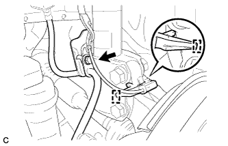
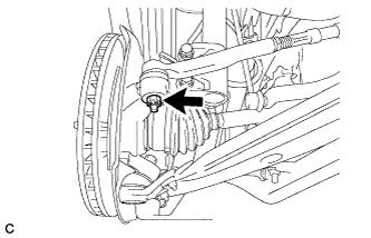
Install the front speed sensor and front flexible hose with the bolt.
- Torque:
- 19 N*m { 194 kgf*cm, 14 ft.*lbf }
Note
-
Do not twist the wire harness for the front speed sensor when installing it.
-
The bolt tightens the brake flexible hose and front speed sensor together. Make sure that the flexible hose is positioned over the front speed sensor.
-
Install the clamp.
-
-
STAKE FRONT AXLE SHAFT NUT
-
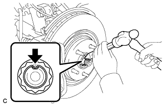
Using a chisel and hammer, stake the front axle shaft nut.
-
-
INSTALL FRONT WHEEL
- Torque:
- 103 N*m { 1050 kgf*cm, 76 ft.*lbf }
-
INSPECT AND ADJUST FRONT WHEEL ALIGNMENT
-
Inspect and adjust the front wheel alignment Click here.
-
-
CHECK FOR SPEED SENSOR SIGNAL
-
Check for the speed sensor signals Click here.
-