REAR DRIVE SHAFT ASSEMBLY REASSEMBLY

-
INSTALL REAR DRIVE SHAFT OUTBOARD JOINT BOOT
-
Hold the drive shaft in a vise between aluminum plates.
Note
Do not overtighten the vise.
-
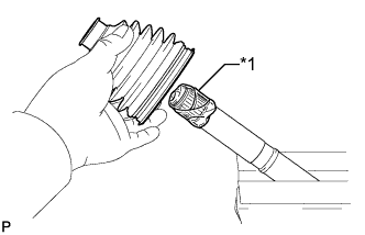
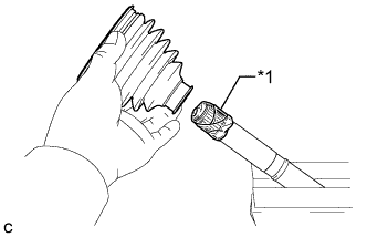
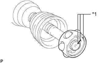
Text in Illustration *1 Protective Tape Wrap the splines of the drive shaft with protective tape to prevent the boot from being damaged.
-
Install new parts to the outboard joint shaft in the following order:
-
Rear drive shaft outboard joint boot clamp
-
Outboard joint boot
-
No. 2 rear drive shaft outboard joint boot clamp
-
-
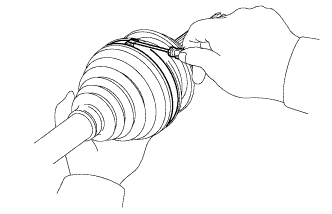
Pack the outboard joint shaft assembly and outboard joint boot with grease from the boot kit.
Grease capacity 71 to 81 g (2.5 to 2.9 oz.)
-
-
INSTALL NO. 2 REAR DRIVE SHAFT OUTBOARD JOINT BOOT CLAMP
-
Hold the drive shaft in a vise between aluminum plates.
Note
Do not overtighten the vise.
-
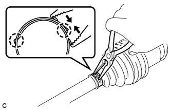
One touch type:
-
Using a screwdriver, install the No. 2 rear drive shaft outboard joint clamp as shown in the illustration.
Note
Do not damage the outboard joint boot.
-
-
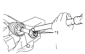
Claw engagement type:
-
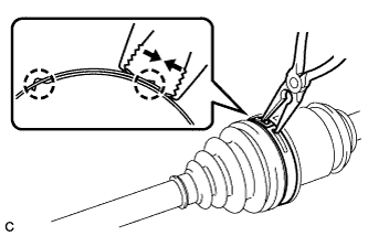
Using needle-nose pliers, install the No. 2 rear drive shaft outboard joint boot clamp as shown in the illustration.
Note
Do not damage the outboard joint boot.
-
-
-
INSTALL REAR DRIVE SHAFT OUTBOARD JOINT BOOT CLAMP
-
One touch type:
-
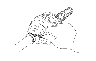
Using a screwdriver, install the rear drive shaft outboard joint clamp as shown in the illustration.
Note
Do not damage the outboard joint boot.
-
-
Claw engagement type:
-
Using needle-nose pliers, install the rear drive shaft outboard joint boot clamp as shown in the illustration.
Note
Do not damage the outboard joint boot.
-
-
-
INSTALL REAR DRIVE SHAFT INBOARD JOINT ASSEMBLY
-
Text in Illustration *1 Protective Tape Wrap the splines of the drive shaft with protective tape to prevent the boot from being damaged.
-
Install new parts to the outboard joint shaft in the following order:
-
No. 2 rear drive shaft inboard joint boot clamp
-
Inboard joint boot
-
Rear drive shaft inboard joint boot clamp
-
-
Text in Illustration *1 Matchmark Align the matchmarks placed before removal and install the inner race to the rear drive outboard joint shaft assembly using a brass bar and a hemmer.
Note
Be careful not to damage the inner race.
-
Using a snap ring expander, install a new shaft snap ring.
-
Text in Illustration *1 Matchmark Align the matchmarks placed before removal and install the cage to the inner race.
-
Install the 6 balls with grease to the inner race.
Note
Be careful not to drop the balls.
Tech Tips
Apply grease onto the balls to keep them from falling.
-
Pack the outboard joint shaft and boot with grease.
Grease capacity 132 to 142 g (4.6 to 5.0 oz.) -
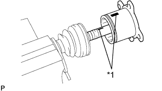
Text in Illustration *1 Matchmark Align the matchmarks and install the inboard joint assembly to the outboard joint shaft assembly.
-
-
INSTALL REAR DRIVE SHAFT INBOARD JOINT BOOT
-
Install the inboard joint boot to the outboard joint shaft.
-
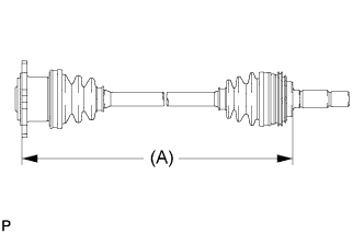
Check whether the drive shaft dimension (A) is within the following specification.
Dimension (A) 619.6 mm (2.03 ft.)
-
-
INSTALL NO. 2 REAR DRIVE SHAFT INBOARD JOINT BOOT CLAMP
-
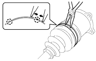
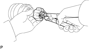
Using needle-nose pliers, install the No. 2 rear drive shaft inboard joint boot clamp as shown in the illustration.
Note
Do not damage the inboard joint boot.
-
-
INSTALL REAR DRIVE SHAFT INBOARD JOINT BOOT CLAMP
-
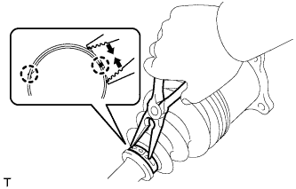
Using needle-nose pliers, install a new rear drive shaft inboard joint boot clamp as shown in the illustration.
Note
Do not damage the inboard joint boot.
-
-
INSPECT REAR DRIVE SHAFT ASSEMBLY
-
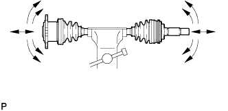
Check that there is no excessive play in the radial direction of the outboard joint.
-
Check that the inboard joint slides smoothly in the thrust direction.
-
Check that there is no excessive play in the radial direction of the inboard joint.
-
Check the boots for damage.
-
Check whether the drive shaft dimension (A) is within the following specification.
Dimension (A) 619.6 mm (2.03 ft.)
-