SHIFT LEVER POSITION SENSOR INSTALLATION

-
INSTALL SHIFT LEVER POSITION SENSOR
-
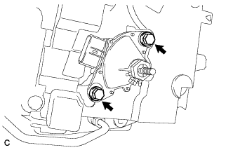
Install the shift lever position sensor to the manual valve shaft.
-
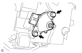
Temporarily install the 2 bolts.
-
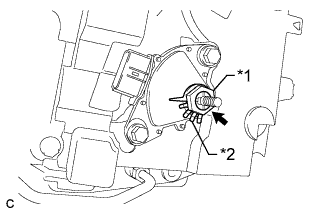
Text in Illustration *1 Lock Nut *2 Lock Plate Place a new lock plate and tighten the nut.
- Torque:
- 6.9 N*m { 70 kgf*cm, 61 in.*lbf }
-
Temporarily install the control shaft lever.
-
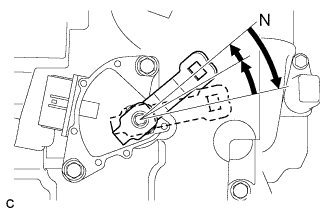
Turn the lever counterclockwise until it stops, then turn it clockwise 2 notches.
-
Remove the control shaft lever.
-
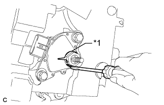
Text in Illustration *1 Neutral Basic Line *2 Protruding Part *3 Range of Play Align the protruding part with the neutral basic line.
Note
There is play on the nut stopper side (protruding part). Align the center point of the range of the play with the neutral basic line.
-
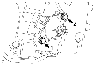
Tighten the 2 bolts in the order shown in the illustration.
- Torque:
- 13 N*m { 133 kgf*cm, 10 ft.*lbf }
-
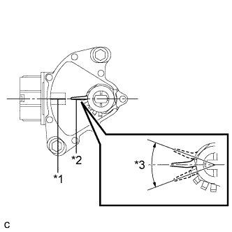
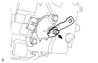
Text in Illustration *1 Lock Plate Using a screwdriver, stake the nut with the lock plate.
-
Install the control shaft lever, washer and nut.
- Torque:
- 13 N*m { 130 kgf*cm, 9 ft.*lbf }
-
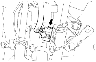
Connect the shift lever position sensor connector.
-
-
CONNECT TRANSMISSION CONTROL CABLE ASSEMBLY
Note
Before installing the transmission control cable assembly, check that the shift lever position sensor and the shift lever are in neutral.
-
Turn back the boot.
-
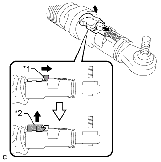
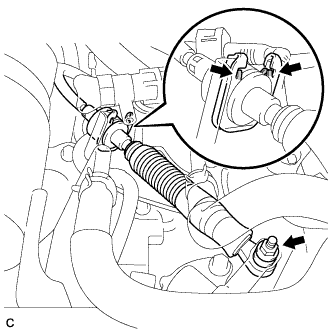
Text in Illustration *1 Slider *2 Lock Piece Slide the slider of the transmission control cable in the direction indicated by the arrow and pull the lock piece outward.
-
Install a new clip to the control cable bracket.
-
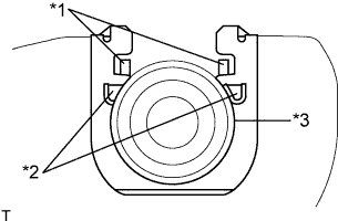
Text in Illustration *1 Claw A *2 Claw B *3 Control Cable Install the control cable to the control cable bracket.
Note
-
Make sure that the claws A on the clip are securely fit into the bracket holes.
-
Make sure that the cable is securely installed inside of the claws B of the clip.
-
-
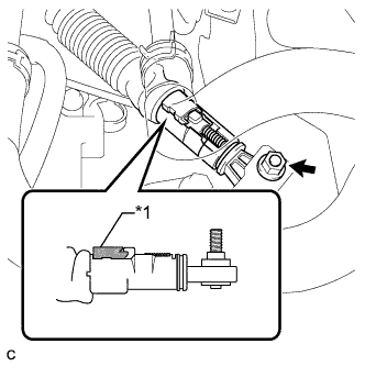
Text in Illustration *1 Lock Piece Connect the transmission control cable to the control shaft lever with the nut.
- Torque:
- 12 N*m { 122 kgf*cm, 9 ft.*lbf }
Note
Check that the lock piece is pulled up.
-
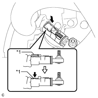
Text in Illustration *1 Lock Piece Push the lock piece into the adjuster case.
Note
-
Check that the shift lever position sensor and the shift lever are in neutral.
-
Securely push in the lock piece until the slider lock is engaged.
-
-
Refit the boot.
-
-
CONNECT CABLE TO NEGATIVE BATTERY TERMINAL
Note
When disconnecting the cable, some systems need to be initialized after the cable is reconnected Click here.
-
INSTALL REAR DECK FLOOR BOX
-

Install the rear deck floor box with the 3 clips.
-
-
INSPECT SHIFT LEVER POSITION SENSOR POSITION
-
Apply the parking brake.
-
Lock the wheels with chocks to secure the vehicle.
-
Turn the power switch on (READY).
-
Move the shift lever to D and release the brake.
Note
Be sure to apply the parking brake and lock the wheels with chocks to secure the vehicle.
-
Slowly move the shift lever to N and measure moving distance (A) of the shift lever from the original point to the gear activation point.
Note
Be sure to move the shift lever slowly.
-
Move the shift lever to R and release the brake.
Note
Be sure to apply the parking brake and lock the wheels with chocks to secure the vehicle.
-
Slowly move the shift lever to N and measure moving distance (B) of the shift lever from the original point to the vehicle activation point.
Note
Be sure to move the shift lever slowly.
-
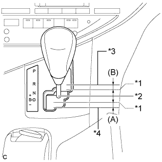
Text in Illustration *1 Gear Activation Point *2 N Position *3 R Position *4 D Position Check that moving distances (A) and (B) shown in the illustration are almost the same.
Tech Tips
-
If moving distances (A) and (B) are almost the same, adjustment of the shift lever position is not necessary.
-
If moving distance (A) is shorter than (B), perform adjustment of the shift lever position*1.
-
If moving distance (B) is shorter than (A), perform adjustment of the shift lever position*2.
-
-
-
ADJUST SHIFT LEVER POSITION SENSOR POSITION
-
If moving distance (A) is shorter than (B)*1:
Text in Illustration *1 Gear Activation Point *2 N Position *3 R Position *4 D Position Tech Tips
If the shift lever is moved from R to N, the moving distance of the shift lever from the original point to the gear activation point becomes longer.
-
Move the shift lever to N.
-
Loosen the 2 bolts.
-
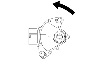
Slightly turn the shift lever position sensor counterclockwise.
-
Tighten the 2 bolts in the order shown in the illustration.
- Torque:
- 13 N*m { 133 kgf*cm, 10 ft.*lbf }
-
Recheck the shift lever position.
-
-
If moving distance (B) is shorter than (A)*2:
Text in Illustration *1 Gear Activation Point *2 N Position *3 R Position *4 D Position Tech Tips
If the shift lever is moved from D to N, the moving distance of the shift lever from the original point to the gear activation point becomes longer.
-
Move the shift lever to N.
-
Loosen the 2 bolts.
-
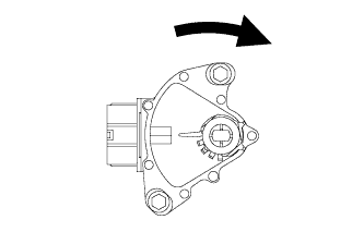
Slightly turn the shift lever position sensor clockwise.
-
Tighten the 2 bolts in the order shown in the illustration.
- Torque:
- 13 N*m { 133 kgf*cm, 10 ft.*lbf }
-
Recheck the shift lever position.
-
-
-
INSPECT SHIFT LEVER POSITION
-
When moving the shift lever from P to R with the power switch on (IG) and the brake pedal depressed, make sure that the shift lever moves smoothly and correctly into position.
-
Turn the power switch on (READY) and make sure that the vehicle moves forward when moving the shift lever from N to D and moves rearward when moving the shift lever to R.
If the operation cannot be performed as specified, inspect the shift lever position sensor and check the shift lever assembly installation condition.
-
-
ADJUST SHIFT LEVER POSITION
-
Apply the parking brake and move the shift lever to N.
Note
Check that the control shaft lever and the shift lever are in neutral.
-
Remove the No. 1 engine under cover.
-
Remove the nut from the control shaft lever.
-
Using a screwdriver, disengage the 4 claws and disconnect the control cable with clip from the control cable bracket.
-
Remove the clip.
-
Turn back the boot.
-
Text in Illustration *1 Slider *2 Lock Piece Slide the slider of the transmission control cable in the direction indicated by the arrow and pull the lock piece outward.
-
Install a new clip to the control cable bracket.
-
Text in Illustration *1 Claw A *2 Claw B *3 Control Cable Install the control cable to the control cable bracket.
Note
-
Make sure that the claws A on the clip are securely fit into the bracket holes.
-
Make sure that the cable is securely installed inside of the claws B of the clip.
-
-
Text in Illustration *1 Lock Piece Connect the transmission control cable to the control shaft lever with the nut.
- Torque:
- 12 N*m { 122 kgf*cm, 9 ft.*lbf }
Note
Check that the lock piece is pulled up.
-
Text in Illustration *1 Lock Piece Push the lock piece into the adjuster case.
Note
-
Check that the shift lever position sensor and the shift lever are in neutral.
-
Securely push in the lock piece until the slider lock is engaged.
-
-
Refit the boot.
-
After adjusting the shift lever position, check the operation and function of the shift lever. If there is a problem, adjust the position again.
-
Install the No. 1 engine under cover.
-
-
INSPECT SHIFT LEVER OPERATION
-
While moving the shift lever from N to each position, check that the lever moves smoothly and that the shift position indicator comes on properly according to the shift lever position.
-
Turn the power switch on (READY) and check the following:
-
When the shift lever is moved to D, the vehicle moves forward.
-
When the shift lever is moved to R, the vehicle moves in reverse.
Note
The vehicle should not move when the shift position indicator is off.
-
-
-
INSTALL NO. 1 ENGINE UNDER COVER