TRANSMISSION CONTROL CABLE REMOVAL

-
PRECAUTION
-
REMOVE INSTRUMENT PANEL REINFORCEMENT ASSEMBLY WITH AIR CONDITIONING UNIT ASSEMBLY
Tech Tips
Refer to the procedure up to Remove Instrument Panel Reinforcement Assembly with Air Conditioning Unit Assembly Click here.
-
REMOVE NO. 1 ENGINE UNDER COVER
-
DRAIN COOLANT (for Inverter)
Note
-
Do not reuse the drained coolant because it may contain foreign objects.
-
Collect the drained coolant and measure its volume to establish a benchmark. When adding coolant, make sure to add more coolant than the measured amount.
-
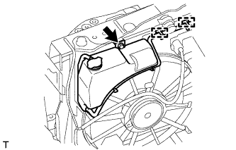
Remove the inverter reserve tank cap.
CAUTION:
To avoid the danger of being burned, do not remove the inverter reserve tank cap while the coolant for the inverter is still hot.
-
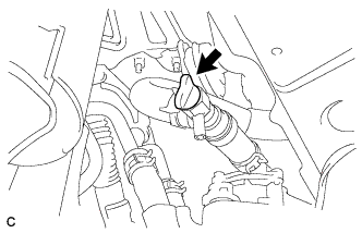
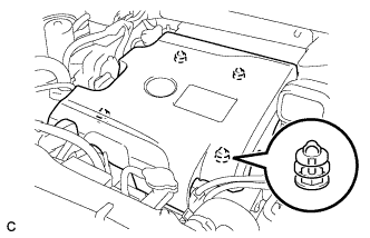
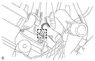
Loosen the drain plug indicated in the illustration and drain the coolant.
CAUTION:
Use caution when handling coolant immediately after driving or in summer because it may be hot.
-
Tighten the plug.
-
-
REMOVE BATTERY SERVICE HOLE COVER
-
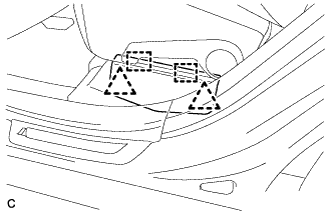
Disengage the 2 clips and 2 guides, and remove the battery service hole cover.
Tech Tips
Because these are 2-piece clips, one side will remain in the bracket when they are being removed.
-
-
REMOVE SERVICE PLUG GRIP
CAUTION:
-
Remove the service plug grip to interrupt a high voltage circuit at the time of the check.
-
Keep the removed service plug grip in your pocket to prevent other technicians from accidentally reconnecting it while you are servicing the vehicle.
-
All the high voltage wiring connectors are orange colored.
-
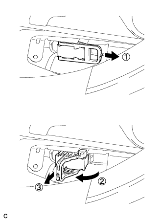
Wear insulated gloves. Remove the service plug grip after sliding the lever of the service plug grip.
CAUTION:
-
Keep the removed service plug grip in your pocket to prevent other technicians from accidentally reconnecting it while you are servicing the vehicle.
-
After disconnecting the service plug grip, wait for at least 10 minutes before touching any of the high-voltage connectors or terminals.
Tech Tips
Waiting for at least 10 minutes is required to discharge the high-voltage capacitor inside the inverter with converter assembly.
-
-
-
REMOVE INTAKE AIR RESONATOR SUB-ASSEMBLY
-
Remove the 3 clamps and Disconnect the water hose from the intake air resonator sub-assembly.
-
Remove the 2 bolts and intake air resonator sub-assembly from the inverter with converter assembly.
-
-
REMOVE INLET NO. 2 AIR CLEANER
-
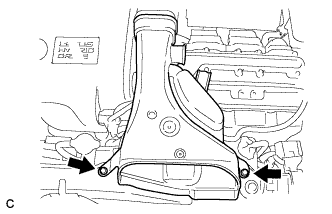
Remove the 2 bolts and inlet No. 2 air cleaner.
-
-
REMOVE V-BANK COVER SUB-ASSEMBLY
-
Hold the front of the V-bank cover sub-assembly and raise it to disengage the 2 retainers on the front of the V-bank cover sub-assembly. Continue to raise the V-bank cover sub-assembly to disengage the 2 retainers on the rear of the V-bank cover sub-assembly and remove the V-bank cover sub-assembly.
Note
Attempting to disengage both front and rear retainers at the same time may cause the V-bank cover sub-assembly to break.
-
-
REMOVE INLET NO. 1 AIR CLEANER
-
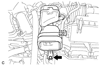
Disconnect the No. 1 fuel vapor feed hose from the inlet No. 1 air cleaner.
-
Remove the bolt and inlet No. 1 air cleaner.
-
-
REMOVE AIR CLEANER ASSEMBLY WITH HOSE
-
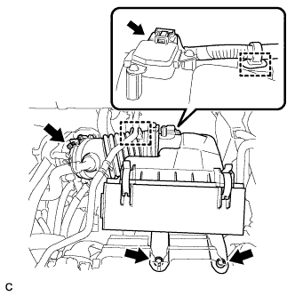
Disconnect the air flow meter connector and harness clamp.
-
Disconnect the No. 1 fuel vapor feed hose from the air cleaner hose.
-
Loosen the band and disconnect the air cleaner hose.
-
Remove the 2 bolts and air cleaner assembly with hose.
-
-
REMOVE NO. 3 INVERTER BRACKET
-
Disconnect the water hose clamp from the No. 3 inverter bracket.
-
Remove the bolt, nut and No. 3 inverter bracket.
-
-
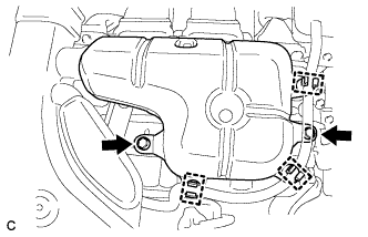
REMOVE INVERTER RESERVE TANK ASSEMBLY
-

Disconnect the hose from the inverter reserve tank.
-
Slide the 3 hose clamps, and disconnect the 3 water hoses from the inverter reserve tank assembly.
-
Remove the bolt, nut and inverter reserve tank assembly.
-
-
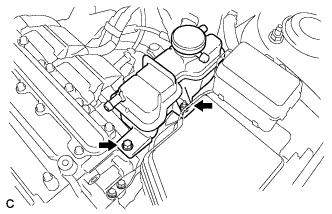
REMOVE NO. 1 INVERTER RESERVE TANK BRACKET
-
Remove the 2 bolts and No. 1 inverter reserve tank bracket.
-
-
REMOVE INVERTER TERMINAL COVER
CAUTION:
Wear insulating gloves.
-
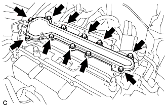
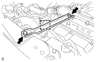
Remove the 11 bolts and inverter terminal cover.
Note
Make sure to pull the inverter cover straight up, as a connector is connected to the bottom of the cover.
-
-
CHECK TERMINAL VOLTAGE
CAUTION:
Wear insulating gloves.
Note
-
Insulate the removed terminals with insulating tape.
-
Do not allow any foreign objects or water to enter the inverter with converter assembly.
-
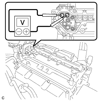
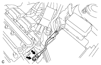
Using a voltmeter, measure the voltage between the 2 terminals.
Standard voltage 0 V Tech Tips
Use a measuring range of DC 750 V or more on the voltmeter.
-
-
DISCONNECT NO. 4 ENGINE WIRE
CAUTION:
Wear insulating gloves.
Note
-
Insulate the removed terminals with insulating tape.
-
Cover the hole where the cable was connected with tape or equivalent (non-residue type) to prevent entry of foreign matter.
-
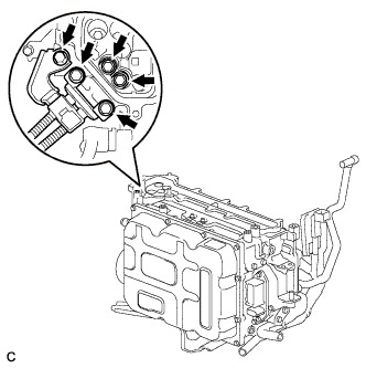
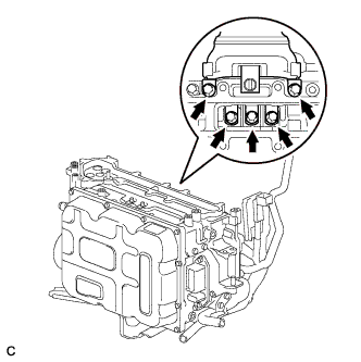
Remove the 5 bolts, and disconnect the No. 4 engine wire (high voltage cables of the air conditioning) from the inverter with converter assembly.
-
-
DISCONNECT NO. 3 WIRE FRAME (for AWD)
CAUTION:
Wear insulating gloves.
Note
-
Insulate the removed terminals with insulating tape.
-
Cover the hole where the cable was connected with tape or equivalent (non-residue type) to prevent entry of foreign matter.
-
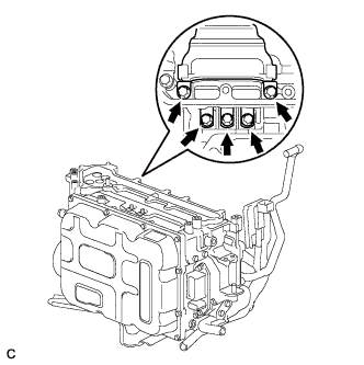
Remove the 5 bolts, and disconnect the No. 3 wire frame (high voltage cables of the rear motor (MGR)) from the inverter with converter assembly.
-
Disconnect the harness clamp.
-
-
DISCONNECT HIGH VOLTAGE CABLE OF FRONT MOTOR
CAUTION:
Wear insulating gloves.
Note
-
Insulate the removed terminals with insulating tape.
-
Cover the hole where the cable was connected with tape or equivalent (non-residue type) to prevent entry of foreign matter.
-
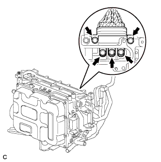
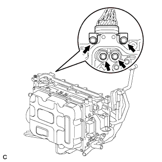
Remove the 5 bolts, and disconnect the high voltage cables of the generator (MG1) from the inverter with converter assembly.
-
Remove the 5 bolts, and disconnect the high voltage cables of the motor (MG2) from the inverter with converter assembly.
-
-
DISCONNECT NO. 3 WIRE FRAME
CAUTION:
Wear insulating gloves.
Note
-
Insulate the removed terminals with insulating tape.
-
Cover the hole where the cable was connected with tape or equivalent (non-residue type) to prevent entry of foreign matter.
-
Remove the 4 bolts, and disconnect the No. 3 wire frame (high voltage cables of the hybrid battery) from the inverter with converter assembly.
-
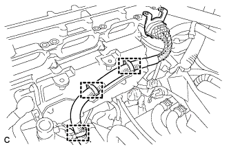
Disconnect the 3 harness clamps.
-
-
INSTALL INVERTER TERMINAL COVER
-
Temporarily install the inverter cover with the 11 bolts to prevent any foreign objects or water from entering the inverter with converter assembly.
-
-
REMOVE NO. 6 INVERTER BRACKET (w/ Bracket)
-
Remove the 2 bolts and No. 6 inverter bracket.
-
-
SEPARATE RELAY BLOCK SUB-ASSEMBLY
-
Disconnect the clamp, and release the relay block sub-assembly.
-
-
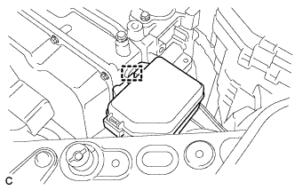
DISCONNECT MG ECU CONNECTOR
CAUTION:
Wear insulating gloves.
Note
-
Insulate the removed terminals with insulating tape.
-
Do not allow any foreign objects or water to enter the inverter with converter assembly.
-
To prevent damage due to static electricity, do not touch the terminals of the disconnected connectors.
-
Raise the lock lever and disconnect the inverter with converter connector.
-
Disconnect the connector from the inverter with converter assembly.
-
-
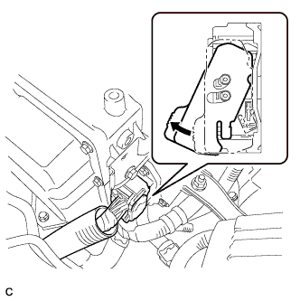
DISCONNECT WATER HOSE
-
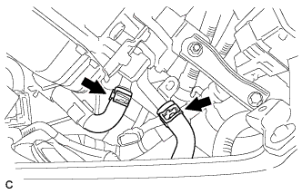
Slide the 2 clamps, and disconnect the 2 water hoses from the inverter with converter assembly.
-
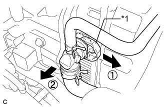
Text in Illustration *1 Retainer Release the retainer and disconnect the water hose from the inverter with converter assembly.
-
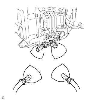
Disconnect the coolant hose from the inverter with converter assembly. Put a piece of cloth in the pipe and in the disconnected hose or cover the pipe and hose with plastic bags as shown in the illustration in order to prevent coolant from spilling around the inverter with converter assembly.
-
-
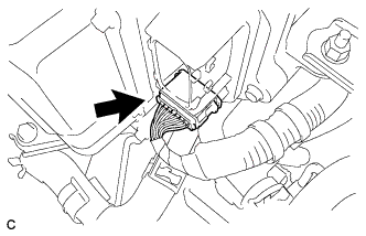
DISCONNECT NO. 2 ENGINE ROOM WIRE
-
Remove the relay block cover.
-
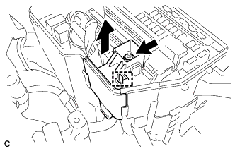
Remove the nut from the No. 2 engine room wire.
-
Release the claw, and disconnect the No. 2 engine room wire.
-
Disconnect the clamp.
-
-
REMOVE NO. 4 INVERTER BRACKET
-
Remove the bolt, nut and No. 4 inverter bracket.
-
-
SEPARATE RADIATOR RESERVE TANK ASSEMBLY
-
Disconnect the 2 clamps and remove the bolt and radiator reserve tank from the radiator.
-
-
SEPARATE CONDENSER
-

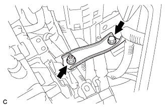
Remove the bolt, and separate the condenser.
-
-
REMOVE INVERTER WITH CONVERTER ASSEMBLY
CAUTION:
Wear insulating gloves.
-
Remove the 2 bolts, nut and inverter with converter assembly.
Note
-
Since the inverter with converter assembly is very heavy, 2 people are needed to remove the inverter with converter assembly. When removing the inverter with converter assembly, do not damage the parts around it.
-
To prevent damage, do not hold the inverter with converter assembly by the connectors.
-
To prevent damage due to static electricity, do not touch the terminals of the disconnected connectors.
-
-
-
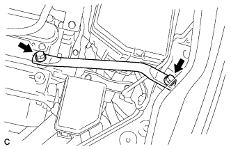
REMOVE TRANSMISSION CONTROL CABLE ASSEMBLY
-
Remove the nut from the control shaft lever.
-
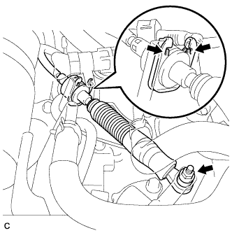
Using a screwdriver, disengage the 4 claws and disconnect the control cable with clip from the control cable bracket.
-
Remove the clip.
-
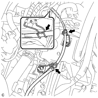
Disconnect the transmission control cable assembly from the 3 control cable brackets.
-
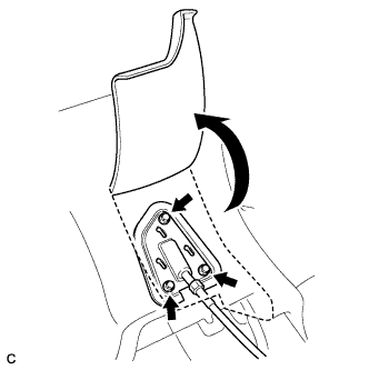
Turn back the carpet.
-
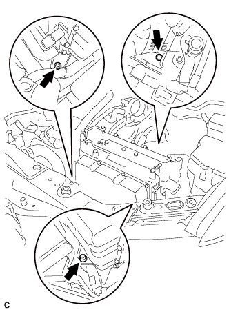
Remove the 3 bolts and pull out the transmission control cable assembly from the body.
-