HYBRID VEHICLE TRANSAXLE UNIT REASSEMBLY

-
INSTALL STRAIGHT PIN
-
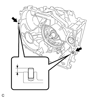
Using a plastic hammer, tap in 2 new straight pins to the hybrid vehicle motor assembly.
Standard Protrusion 7.0 to 8.0 mm (0.276 to 0.315 in.)
-
-
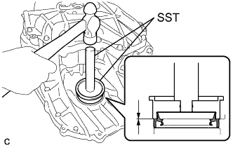
INSTALL TAPERED ROLLER BEARING (INNER RACE) (for LH Side)
-
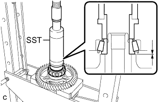
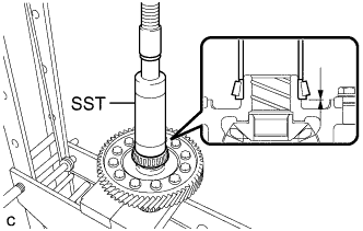
Using SST and a press, install a new tapered roller bearing (inner race) to the counter driven gear sub-assembly.
- SST
- 09316-60011 ( 09316-00011, 09316-00071 )
Note
Be sure to install the tapered roller bearing (inner race) so that there is no clearance between the tapered roller bearing (inner race) and the counter driven gear sub-assembly.
Tech Tips
When adjusting the preload is not necessary, the tapered roller bearing (inner race) can be reused.
-
-
INSTALL TAPERED ROLLER BEARING (INNER RACE) (for RH Side)
-
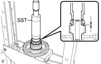
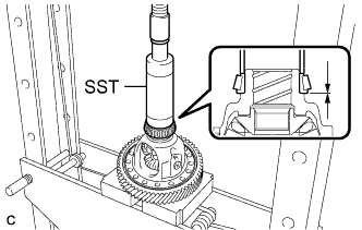
Using SST and a press, install a new tapered roller bearing (inner race) to the counter driven gear sub-assembly.
- SST
- 09316-60011 ( 09316-00011, 09316-00071 )
Note
Be sure to install the tapered roller bearing (inner race) so that there is no clearance between the tapered roller bearing (inner race) and the differential drive pinion.
Tech Tips
When adjusting the preload is not necessary, the tapered roller bearing (inner race) can be reused.
-
-
INSTALL LOCK NUT
-
Secure the counter driven gear sub-assembly in a vise using aluminum plates.
Note
Be careful not to damage the counter driven gear sub-assembly in the vise.
-
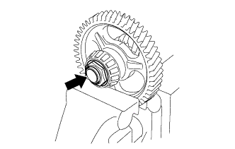
Using a 41 mm deep socket wrench, install a new lock nut to the counter driven gear sub-assembly.
- Torque:
- 280 N*m { 2855 kgf*cm, 207 ft.*lbf }
-
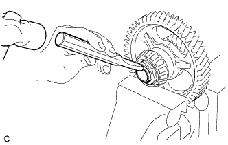
Using a chisel and hammer, stake the lock nut.
-
-
INSTALL TAPERED ROLLER BEARING (INNER RACE) (for LH Side)
-
Using SST and a press, install a new tapered roller bearing (inner race) to the differential case sub-assembly.
- SST
- 09316-60011 ( 09316-00011 )
Note
Be sure to install the tapered roller bearing (inner race) so that there is no clearance between the tapered roller bearing (inner race) and the differential case sub-assembly.
Tech Tips
When adjusting the preload is not necessary, the tapered roller bearing (inner race) can be reused.
-
-
INSTALL TAPERED ROLLER BEARING (INNER RACE) (for RH Side)
-
Using SST and a press, install a new tapered roller bearing (inner race) to the differential case sub-assembly.
- SST
- 09316-60011 ( 09316-00011 )
Note
Be sure to install the tapered roller bearing (inner race) so that there is no clearance between the tapered roller bearing (inner race) and the differential case sub-assembly.
Tech Tips
When adjusting the preload is not necessary, the tapered roller bearing (inner race) can be reused.
-
-
INSTALL TAPERED ROLLER BEARING (OUTER RACE) (for RH Side)
-
Using SST and a hammer, install the tapered roller bearing (outer race) and differential case RH shim to the hybrid vehicle generator assembly.
- SST
- 09950-60020 ( 09951-00890 )
- 09950-70010 ( 09951-07200 )
Note
-
After adjusting the preload, replace the differential case RH shim with a new one.
-
If the differential case RH shim or tapered roller bearing (outer race) is deformed or damaged, replace it with a new one.
-
Be sure to install the tapered roller bearing (outer race) so that there is no clearance between the tapered roller bearing (outer race) and the hybrid vehicle generator assembly.
-
-
INSTALL TAPERED ROLLER BEARING (OUTER RACE) (for LH Side)
-
Using SST and a hammer, install the tapered roller bearing (outer race) to the hybrid vehicle motor assembly.
- SST
- 09950-60020 ( 09951-00910 )
- 09950-70010 ( 09951-07200 )
Note
-
If the tapered roller bearing (outer race) is deformed or damaged, replace it with a new one.
-
Be sure to install the tapered roller bearing (outer race) so that there is no clearance between the tapered roller bearing (outer race) and the hybrid vehicle motor assembly.
-
-
ADJUST PRELOAD (for Differential Case Sub-assembly)
Note
-
Tapered roller bearing (inner race) (for LH side and RH side) for differential case sub-assembly
-
Tapered roller bearing (outer race) (for LH side and RH side) for differential case sub-assembly
-
Tapered roller bearing (inner race) (for LH side and RH side) for counter driven gear sub-assembly
-
Tapered roller bearing (outer race) (for LH side and RH side) for counter driven gear sub-assembly
-
Adjust the preload in the following situations:
-
When replacing the hybrid vehicle generator assembly with a new one
-
When replacing the differential case sub-assembly with a new one
-
When replacing the counter driven gear sub-assembly with a new one
-
When replacing the tapered roller bearing (inner race or outer race) with a new one
Replace the following parts with new ones before adjusting the preload.
-
Install the differential case sub-assembly to the hybrid vehicle motor assembly.
-
Install the No. 1 engine hanger and No. 2 engine hanger with the 2 bolts and washer as shown in the illustration.
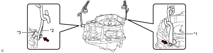
Text in Illustration *1 No. 1 Engine Hanger *2 No. 2 Engine Hanger *3 Washer - - - Torque:
- 43 N*m { 438 kgf*cm, 32 ft.*lbf }
Part Name Part No. No. 1 Engine Hanger 12281-37050 No. 2 Engine Hanger 12282-37040 Bolt 91552-81050 Tech Tips
When installing the No. 1 engine hanger, use a washer with an appropriate thickness so that the No. 1 engine hanger will not interfere with the installation surface of the hybrid vehicle generator assembly.
-
Using the sling device and chain block, install the hybrid vehicle generator assembly to the hybrid vehicle motor assembly.
-
Install the 9 bolts to the hybrid vehicle generator assembly.
- Torque:
- 29 N*m { 300 kgf*cm, 22 ft.*lbf }
-
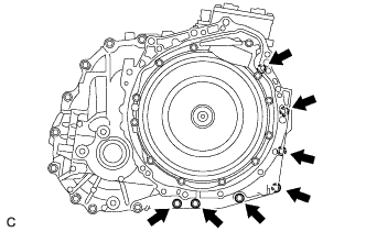
Install the 7 bolts to the hybrid vehicle generator assembly.
- Torque:
- 29 N*m { 300 kgf*cm, 22 ft.*lbf }
-
Install the 3 bolts to the hybrid vehicle motor assembly.
- Torque:
- 21 N*m { 214 kgf*cm, 15 ft.*lbf }
Tech Tips
Reuse the bolts to remove the hybrid vehicle generator assembly after adjusting the preload.
-
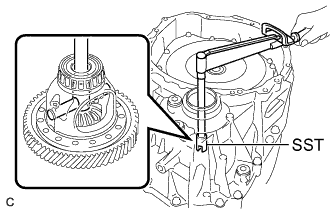
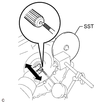
Using SST and a torque wrench, measure and record the starting torque of the differential case sub-assembly.
- SST
- 09564-33010
Standard Preload Starting Torque 1.0 to 1.5 N*m (11 to 15 kgf*cm, 9 to 13 in.*lbf) Note
-
Before measurement, turn the differential pinion shaft in both directions to settle the bearings.
-
Make a note of the starting torque that will be used when adjusting the preload of the counter driven gear sub-assembly.
-
If the differential case RH shim or tapered roller bearing (outer race) is deformed or damaged, replace it with a new one.
Tech Tips
If the value is not as specified, replace the differential case RH shim with one of the correct thickness.
Differential Case RH Shim Thickness Part No. Thickness (mm (in.)) Part No. Thickness (mm (in.)) 90564-74001 2.00 (0.07874) 90564-74023 2.44 (0.09606) 90564-74002 2.02 (0.07953) 90564-74024 2.46 (0.09685) 90564-74003 2.04 (0.08031) 90564-74025 2.48 (0.09764) 90564-74004 2.06 (0.08110) 90564-74026 2.50 (0.09843) 90564-74005 2.08 (0.08189) 90564-74027 2.52 (0.09921) 90564-74006 2.10 (0.08268) 90564-74028 2.54 (0.1000) 90564-74007 2.12 (0.08346) 90564-74029 2.56 (0.1008) 90564-74008 2.14 (0.08425) 90564-74030 2.58 (0.1016) 90564-74009 2.16 (0.08504) 90564-74031 2.60 (0.1024) 90564-74010 2.18 (0.08583) 90564-74032 2.62 (0.1031) 90564-74011 2.20 (0.08661) 90564-74033 2.64 (0.1039) 90564-74012 2.22 (0.08740) 90564-74034 2.66 (0.1047) 90564-74013 2.24 (0.08819) 90564-74035 2.68 (0.1055) 90564-74014 2.26 (0.08898) 90564-74036 2.70 (0.1063) 90564-74015 2.28 (0.08976) 90564-74037 2.72 (0.1071) 90564-74016 2.30 (0.09055) 90564-74038 2.74 (0.1079) 90564-74017 2.32 (0.09134) 90564-74039 2.76 (0.1087) 90564-74018 2.34 (0.09213) 90564-74040 2.78 (0.1094) 90564-74019 2.36 (0.09291) 90564-74041 2.80 (0.1102) 90564-74020 2.38 (0.09370) 90564-74042 2.82 (0.1110) 90564-74021 2.40 (0.09449) 90564-74043 2.84 (0.1118) 90564-74022 2.42 (0.09528) 90564-74044 2.86 (0.1126) -
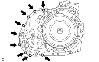
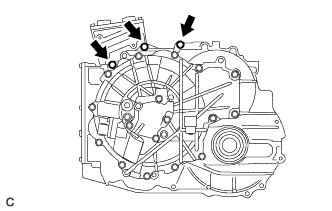
Remove the 19 bolts from the hybrid vehicle motor assembly and hybrid vehicle generator assembly.
-
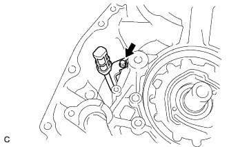
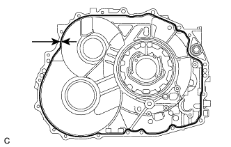
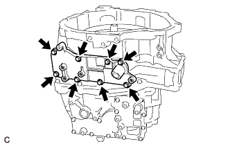
While lifting the hybrid vehicle generator assembly with a chain, tap the areas shown in the illustration with a plastic hammer and separate the hybrid vehicle generator assembly from the hybrid vehicle motor assembly.
-
While lifting the hybrid vehicle generator assembly with a chain, remove it from the hybrid vehicle motor assembly.
Note
-
Lift the hybrid vehicle generator assembly straight up.
-
If the hybrid vehicle generator assembly is tilted, return it to the original position before removing.
-
-
Remove the differential case sub-assembly from the hybrid vehicle motor assembly.
-
Remove the 2 bolts, washer, No. 1 engine hanger and No. 2 engine hanger from the hybrid vehicle generator assembly.
-
-
INSTALL TAPERED ROLLER BEARING (OUTER RACE) (for RH Side)
-
Using SST and a hammer, install the tapered roller bearing (outer race) and counter driven gear shim to the hybrid vehicle generator assembly.
- SST
- 09950-60020 ( 09951-00730 )
- 09950-70010 ( 09951-07200 )
Note
-
After adjusting the preload, replace the counter driven gear shim with a new one.
-
If the counter driven gear shim or tapered roller bearing (outer race) is deformed or damaged, replace it with a new one.
-
Be sure to install the tapered roller bearing (outer race) so that there is no clearance between the tapered roller bearing (outer race) and the hybrid vehicle generator assembly.
-
-
INSTALL TAPERED ROLLER BEARING (OUTER RACE) (for LH Side)
-
Using SST and a hammer, install the tapered roller bearing (outer race) to the hybrid vehicle motor assembly.
- SST
- 09950-60020 ( 09951-00710 )
- 09950-70010 ( 09951-07200 )
Note
-
If the tapered roller bearing (outer race) is deformed or damaged, replace it with a new one.
-
Be sure to install the tapered roller bearing (outer race) so that there is no clearance between the tapered roller bearing (outer race) and the hybrid vehicle motor assembly.
-
-
ADJUST PRELOAD (for Counter Driven Gear Sub-assembly)
-
Install the counter driven gear sub-assembly to the hybrid vehicle motor assembly.
-
Install the differential case sub-assembly to the hybrid vehicle motor assembly.
-
Install the No. 1 engine hanger and No. 2 engine hanger with the 2 bolts and washer as shown in the illustration.
Text in Illustration *1 No. 1 Engine Hanger *2 No. 2 Engine Hanger *3 Washer - - - Torque:
- 43 N*m { 438 kgf*cm, 32 ft.*lbf }
Part Name Part No. No. 1 Engine Hanger 12281-37050 No. 2 Engine Hanger 12282-37040 Bolt 91552-81050 Tech Tips
When installing the No. 1 engine hanger, use a washer with an appropriate thickness so that the No. 1 engine hanger will not interfere with the installation surface of the hybrid vehicle generator assembly.
-
Using the sling device and chain block, install the hybrid vehicle generator assembly to the hybrid vehicle motor assembly.
-
Install the 9 bolts to the hybrid vehicle generator assembly.
- Torque:
- 29 N*m { 300 kgf*cm, 22 ft.*lbf }
-
Install the 7 bolts to the hybrid vehicle generator assembly.
- Torque:
- 29 N*m { 300 kgf*cm, 22 ft.*lbf }
-
Install the 3 bolts to the hybrid vehicle motor assembly.
- Torque:
- 21 N*m { 214 kgf*cm, 15 ft.*lbf }
Tech Tips
Reuse the bolts to remove the hybrid vehicle generator assembly after adjusting the preload.
-
Using SST and a torque wrench, measure the starting torque of the differential case sub-assembly.
- SST
- 09564-33010
Standard Preload Starting Torque TD + 3.8 to 4.8 N*m (39 to 49 kgf*cm, 34 to 42 in.*lbf) TD: Starting torque when adjusting the preload of the differential case sub-assembly
Note
-
Before measurement, turn the differential pinion shaft in both directions to settle the bearings.
-
If the counter driven gear shim or tapered roller bearing (outer race) is deformed or damaged, replace it with a new one.
Tech Tips
If the value is not as specified, replace the counter driven gear shim with one of the correct thickness.
Counter Driven Gear Shim Thickness Part No. Thickness (mm (in.)) Part No. Thickness (mm (in.)) 90564-60100 1.75 (0.06890) 90564-60127 2.29 (0.09016) 90564-60101 1.77 (0.06968) 90564-60128 2.31 (0.09094) 90564-60102 1.79 (0.07047) 90564-60129 2.33 (0.09173) 90564-60103 1.81 (0.07126) 90564-60130 2.35 (0.09252) 90564-60104 1.83 (0.07205) 90564-60131 2.37 (0.09331) 90564-60105 1.85 (0.07283) 90564-60132 2.39 (0.09409) 90564-60106 1.87 (0.07362) 90564-60133 2.41 (0.09488) 90564-60107 1.89 (0.07441) 90564-60134 2.43 (0.09567) 90564-60108 1.91 (0.07520) 90564-60135 2.45 (0.09646) 90564-60109 1.93 (0.07598) 90564-60136 2.47 (0.09724) 90564-60110 1.95 (0.07677) 90564-60137 2.49 (0.09803) 90564-60111 1.97 (0.07756) 90564-60138 2.51 (0.09882) 90564-60112 1.99 (0.07835) 90564-60139 2.53 (0.09961) 90564-60113 2.01 (0.07913) 90564-60140 2.55 (0.10039) 90564-60114 2.03 (0.07992) 90564-60141 2.57 (0.10118) 90564-60115 2.05 (0.08071) 90564-60142 2.59 (0.10197) 90564-60116 2.07 (0.08150) 90564-60143 2.61 (0.10276) 90564-60117 2.09 (0.08228) 90564-60144 2.63 (0.10354) 90564-60118 2.11 (0.08307) 90564-60145 2.65 (0.10433) 90564-60119 2.13 (0.08386) 90564-60146 2.67 (0.10512) 90564-60120 2.15 (0.08465) 90564-60147 2.69 (0.10591) 90564-60121 2.17 (0.08543) 90564-60148 2.71 (0.10669) 90564-60122 2.19 (0.08622) 90564-60149 2.73 (0.10748) 90564-60123 2.21 (0.08701) 90564-60150 2.75 (0.10827) 90564-60124 2.23 (0.08780) 90564-60151 2.77 (0.10905) 90564-60125 2.25 (0.08858) 90564-60152 2.79 (0.10984) 90564-60126 2.27 (0.08937) 90564-60153 2.81 (0.11063) -
Remove the 19 bolts from the hybrid vehicle motor assembly and hybrid vehicle generator assembly.
-
While lifting the hybrid vehicle generator assembly with a chain, tap the areas shown in the illustration with a plastic hammer and separate the hybrid vehicle generator assembly from the hybrid vehicle motor assembly.
-
While lifting the hybrid vehicle generator assembly with a chain, remove it from the hybrid vehicle motor assembly.
Note
-
Lift the hybrid vehicle generator assembly straight up.
-
If the hybrid vehicle generator assembly is tilted, return it to the original position before removing.
-
-
Remove the differential case sub-assembly from the hybrid vehicle motor assembly.
-
Remove the counter driven gear sub-assembly from the hybrid vehicle motor assembly.
-
Remove the 2 bolts, washer, No. 1 engine hanger and No. 2 engine hanger from the hybrid vehicle generator assembly.
-
-
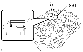
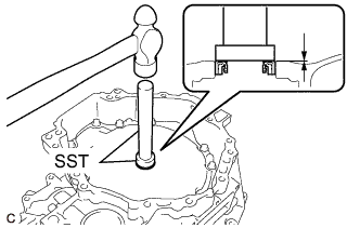
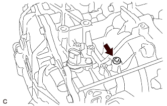
INSTALL PARKING LOCK SHAFT TYPE T OIL SEAL
-
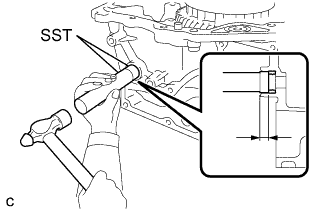
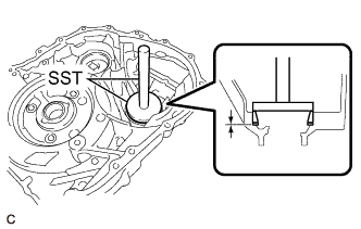
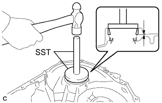
Using SST and a hammer, install a new parking lock shaft type T oil seal to the hybrid vehicle motor assembly.
- SST
- 09950-60010 ( 09951-00210 )
- 09950-70010 ( 09951-07100 )
Standard Depth 6.8 to 7.7 mm (0.268 to 0.303 in.) -
Coat the lip of the parking lock shaft type T oil seal with a small amount of MP grease.
-
-
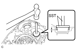
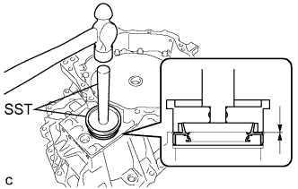
INSTALL HYBRID VEHICLE TRANSAXLE ASSEMBLY TYPE T OIL SEAL (for LH Side)
-
Using SST and a hammer, install a new hybrid vehicle transaxle assembly type T oil seal to the hybrid vehicle motor assembly.
- SST
- 09223-15020
- 09950-70010 ( 09951-07150 )
Standard Depth -0.5 to 0.5 mm (-0.0197 to 0.0197 in.) Note
-
Do not allow foreign matter to attach to the hybrid vehicle transaxle assembly type T oil seal lip.
-
Do not install the hybrid vehicle transaxle assembly type T oil seal at an angle.
-
Coat the lip of the hybrid vehicle transaxle assembly type T oil seal with a small amount of MP grease.
-
-
INSTALL TRANSMISSION OIL STRAINER
-
Coat a new O-ring with ATF and install it to the transmission oil strainer.
Note
Be careful not to damage the O-ring.
-
Install the transmission oil strainer to the hybrid vehicle motor assembly with the bolt.
- Torque:
- 8.4 N*m { 86 kgf*cm, 74 in.*lbf }
-
-
INSTALL PLANETARY OIL RECEIVER
-
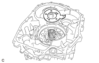
Install the planetary oil receiver to the hybrid vehicle motor assembly.
-
-
INSTALL NO. 1 REAR PLANETARY GEAR ASSEMBLY
-
Install the No. 1 rear planetary gear assembly to the rear planetary sun gear.
-
-
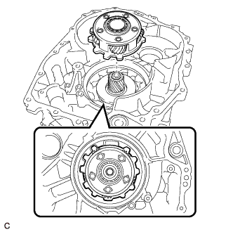
INSTALL COUNTER DRIVE GEAR SUB-ASSEMBLY
-
Install the counter drive gear sub-assembly to the No. 1 rear planetary gear assembly.
-
-
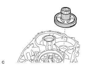
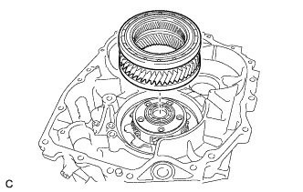
INSTALL COUNTER DRIVEN GEAR SUB-ASSEMBLY
-
Install the counter driven gear sub-assembly to the hybrid vehicle motor assembly.
-
-
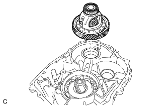
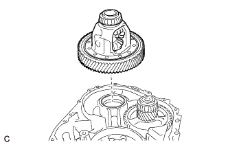
INSTALL DIFFERENTIAL CASE SUB-ASSEMBLY
-
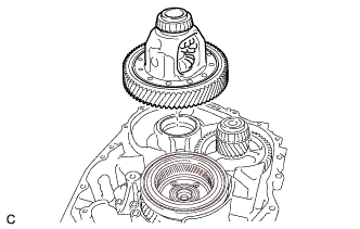
Install the differential case sub-assembly to the hybrid vehicle motor assembly.
-
-
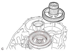
INSTALL THRUST NEEDLE ROLLER BEARING
-
Apply ATF to the contact surfaces of the thrust needle roller bearing.
-
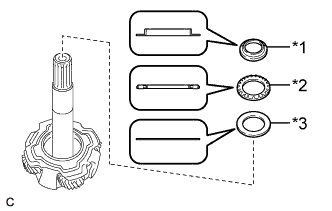
Text in Illustration *1 Thrust Bearing Race *2 Thrust Needle Roller Bearing *3 No. 1 Thrust Bearing Race Install the No. 1 thrust bearing race, thrust needle roller bearing and thrust bearing race to the input shaft assembly.
-
-
INSTALL INPUT SHAFT ASSEMBLY
-
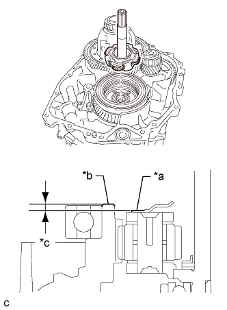
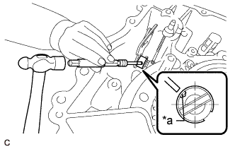
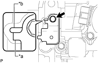
Text in Illustration *a Surface (a) of input shaft assembly *b Surface (b) of counter drive gear sub-assembly *c Approximately 4 mm (0.157 in.) Install the input shaft assembly to the counter drive gear sub-assembly.
Note
Make sure that the surface (a) of the input shaft assembly is positioned under the surface (b) of the counter drive gear sub-assembly.
-
-
INSTALL PLANETARY SUN GEAR
-
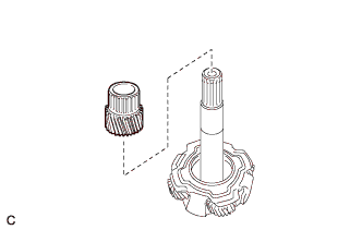
Install the planetary sun gear to the input shaft assembly.
-
Select a planetary sun gear snap ring.
-
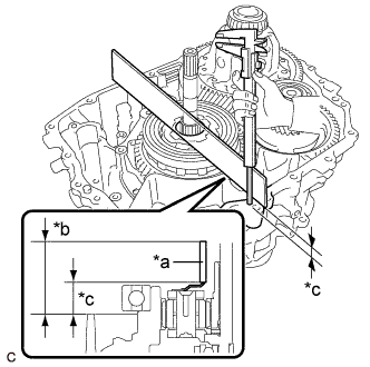
Text in Illustration *a Straightedge *b Measured area *c Dimension A Using a straightedge and vernier caliper, measure dimension A shown in the illustration.
Dimension A Measured value - Straightedge thickness -
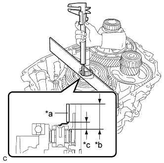
Text in Illustration *a Straightedge *b Measured area *c Dimension B Using a straightedge and vernier caliper, measure dimension B shown in the illustration.
Dimension B Measured value - Straightedge thickness Note
Measure the dimensions without a planetary sun gear snap ring installed.
-
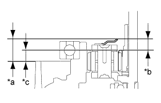
Text in Illustration *a Dimension A *b Dimension B *c Dimension C Calculate dimension C.
Dimension C Dimension A - Dimension B -
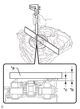
Text in Illustration *a Straightedge *b Measured area *c Dimension D Using a straightedge and vernier caliper, measure dimension D shown in the illustration.
Dimension D Measured value - Straightedge thickness -
Select a planetary sun gear snap ring.
Standard Value Planetary sun gear snap ring thickness = (Dimension D - Dimension C) - (0.1 to 0.2 mm (0.00394 to 0.00787 in.)) Note
There should be a clearance of 0.1 to 0.2 mm (0.00394 to 0.00787 in.) for the input shaft assembly. Therefore, use the above formula when selecting a planetary sun gear snap ring.
Planetary Sun Gear Snap Ring Thickness Part No. Thickness (mm (in.)) Part No. Thickness (mm (in.)) 90520-37017 3.88 (0.153) 90520-37033 4.33 (0.170) 90520-37018 3.91 (0.154) 90520-37034 4.36 (0.172) 90520-37019 3.94 (0.155) 90520-37035 4.39 (0.173) 90520-37020 3.97 (0.156) 90520-37036 4.42 (0.174) 90520-37021 4.00 (0.157) 90520-37037 4.45 (0.175) 90520-37022 4.03 (0.159) 90520-37038 4.48 (0.176) 90520-37023 4.06 (0.160) 90520-37039 4.51 (0.178) 90520-37024 4.09 (0.161) 90520-37040 4.54 (0.179) 90520-37025 4.12 (0.162) 90520-37041 4.57 (0.180) 90520-37026 4.15 (0.163) 90520-37042 4.60 (0.181) 90520-37027 4.18 (0.165) 90520-37043 4.63 (0.182) 90520-37028 4.21 (0.166) 90520-37044 4.66 (0.183) 90520-37029 4.24 (0.167) 90520-37045 4.69 (0.185) 90520-37030 4.27 (0.168) 90520-37046 4.72 (0.186) 90520-37031 4.30 (0.169) - -
-
-
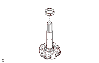
Install the planetary sun gear snap ring to the input shaft assembly.
-
-
INSTALL NO. 1 TRANSMISSION MAGNET
-
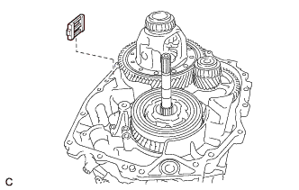
Install the No. 1 transmission magnet to the hybrid vehicle motor assembly.
-
-
INSTALL PARKING LOCK ROD SUB-ASSEMBLY
-
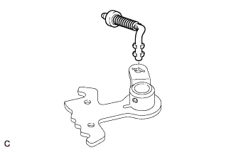
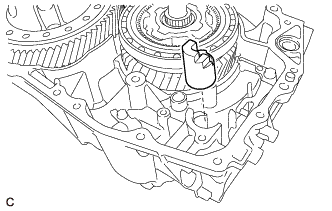
Align the slot with the protrusions on the No. 1 parking lock lever sub-assembly and install the parking lock rod sub-assembly.
-
-
INSTALL NO. 1 PARKING LOCK SHAFT
-
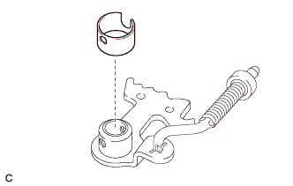
Install a new spacer to the No. 1 parking lock lever sub-assembly.
-
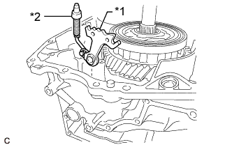
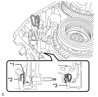
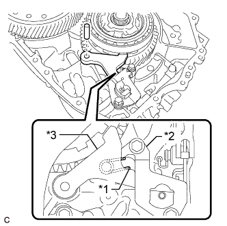
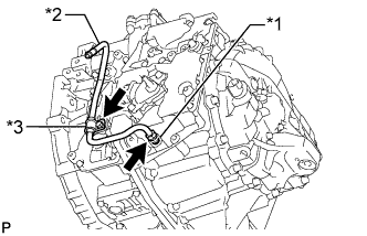
Text in Illustration *1 No. 1 Parking Lock Lever Sub-assembly *2 Parking Lock Rod Sub-assembly Install the No. 1 parking lock lever sub-assembly and parking lock rod sub-assembly to the hybrid vehicle motor assembly.
-
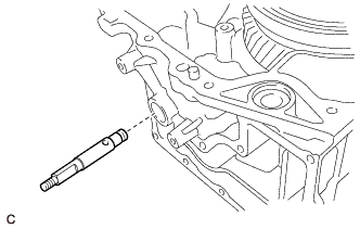
Install the No. 1 parking lock shaft to the hybrid vehicle motor assembly.
-
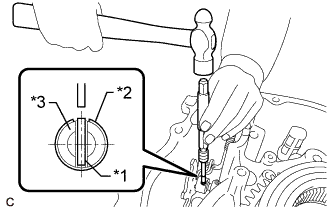
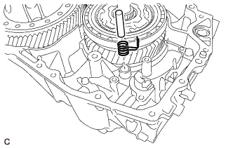
Text in Illustration *1 Slotted Spring Pin *2 Spacer *3 No. 1 Parking Lock Shaft Using a 5 mm pin punch and hammer, drive in a new slotted spring pin to the No. 1 parking lock shaft.
-
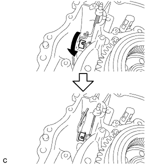
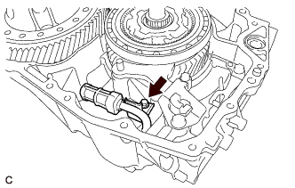
Turn the spacer as shown in the illustration.
-
Text in Illustration *a Stake point Using a 3 mm pin punch and hammer, stake the spacer.
Note
After staking the spacer, make sure that it is firmly secured.
-
-
INSTALL RETAINER SPRING
-
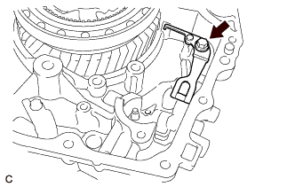
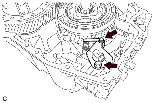
Text in Illustration *1 Retainer Spring *2 No. 1 Parking Lock Shaft *3 Hybrid Vehicle Motor Assembly Install the retainer spring to the hybrid vehicle motor assembly and No. 1 parking lock shaft.
Note
Check that the retainer spring is securely installed to the groove of the No. 1 parking lock shaft.
-
-
INSTALL MANUAL DETENT SPRING SUB-ASSEMBLY
-
Install the manual detent spring sub-assembly to the hybrid vehicle motor assembly with the bolt.
- Torque:
- 26 N*m { 260 kgf*cm, 19 ft.*lbf }
-
-
INSTALL PARKING LOCK SLEEVE
-
Install the parking lock sleeve to the hybrid vehicle motor assembly.
-
-
INSTALL TORSION SPRING
-
Install the parking lock pawl shaft and torsion spring to the hybrid vehicle motor assembly.
-
-
INSTALL PAWL STOPPER PLATE
-
Install the pawl stopper plate to the hybrid vehicle motor assembly with the 2 bolts.
- Torque:
- 26 N*m { 260 kgf*cm, 19 ft.*lbf }
-
-
INSTALL PARKING LOCK PAWL
-
Text in Illustration *1 Torsion Spring *2 Pawl Stopper Plate *3 Parking Lock Pawl Install the parking lock pawl to the hybrid vehicle motor assembly with the parking lock pawl shaft.
Note
Make sure the torsion spring is attached to the parking lock pawl and pawl stopper plate.
-
-
INSTALL NO. 2 TRANSMISSION OIL STRAINER
-

Coat a new O-ring with ATF and install it to the No. 2 transmission oil strainer.
Note
Be careful not to damage the O-ring.
-
Install the No. 2 transmission oil strainer to the hybrid vehicle motor assembly with the bolt.
- Torque:
- 8.4 N*m { 86 kgf*cm, 74 in.*lbf }
-
-
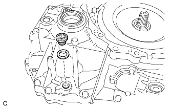
INSTALL INPUT SHAFT TYPE T OIL SEAL
-
Using SST and a hammer, install a new input shaft type T oil seal to the hybrid vehicle generator assembly.
- SST
- 09950-60010 ( 09951-00390 )
- 09950-70010 ( 09951-07150 )
Standard Depth 1.0 to 1.8 mm (0.0394 to 0.0709 in.) Note
-
Do not allow foreign matter to attach to the input shaft type T oil seal lip.
-
Do not install the input shaft type T oil seal at an angle.
-
Coat the lip of the input shaft type T oil seal with a small amount of MP grease.
-
-
INSTALL HYBRID VEHICLE TRANSAXLE ASSEMBLY TYPE T OIL SEAL (for RH Side)
-
Using SST and a hammer, install a new hybrid vehicle transaxle assembly type T oil seal to the hybrid vehicle generator assembly.
- SST
- 09387-00010
- 09950-70010 ( 09951-07150 )
Standard Depth -0.5 to 0.5 mm (-0.0197 to 0.0197 in.) Note
-
Do not allow foreign matter to attach to the hybrid vehicle transaxle assembly type T oil seal lip.
-
Do not install the hybrid vehicle transaxle assembly type T oil seal at an angle.
-
Coat the lip of the hybrid vehicle transaxle assembly type T oil seal with a small amount of MP grease.
-
-
INSTALL HYBRID VEHICLE GENERATOR ASSEMBLY
-
Clean and degrease the bolts and bolt holes.
-
Clean the hybrid vehicle motor assembly installation surface of the hybrid vehicle generator assembly.
Note
-
Do not allow any remaining seal packing to enter the hybrid vehicle generator assembly.
-
Do not damage the installation surface.
-
-
Clean the hybrid vehicle generator assembly installation surface of the hybrid vehicle motor assembly.
Note
-
Do not allow any remaining seal packing to enter the hybrid vehicle motor assembly.
-
Do not damage the installation surface.
-
-
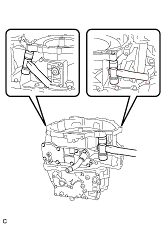
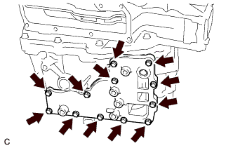
Apply seal packing to the hybrid vehicle motor assembly as shown in the illustration.
Text in Illustration 
Seal Packing Seal Packing Toyota Genuine Seal Packing 1281, Three Bond 1281 or equivalent Standard Seal Diameter 1.5 mm (0.0591 in.) or more Note
-
Clean the installation surfaces.
-
Check and clean the bolts and bolt holes.
-
Install the hybrid vehicle generator assembly within 3 minutes and tighten the bolts within 10 minutes of applying the seal packing.
-
Make sure to overlap the start and the end points of the seal packing.
-
Do not add fluid for at least 2 hours after installing the hybrid vehicle generator assembly.
-
Do not turn the power switch on (READY) for at least 2 hours after installing the hybrid vehicle generator assembly to prevent the engine from starting.
-
-
Install the No. 1 engine hanger and No. 2 engine hanger with the 2 bolts and washer as shown in the illustration.
Text in Illustration *1 No. 1 Engine Hanger *2 No. 2 Engine Hanger *3 Washer - - - Torque:
- 43 N*m { 438 kgf*cm, 32 ft.*lbf }
Part Name Part No. No. 1 Engine Hanger 12281-37050 No. 2 Engine Hanger 12282-37040 Bolt 91552-81050 Tech Tips
When installing the No. 1 engine hanger, use a washer with an appropriate thickness so that the No. 1 engine hanger will not interfere with the installation surface of the hybrid vehicle generator assembly.
-
Using the sling device and chain block, install the hybrid vehicle generator assembly to the hybrid vehicle motor assembly.
Note
-
Lift the hybrid vehicle generator assembly straight up.
-
Do not damage the input shaft type T oil seal with the input shaft assembly.
-
If it is difficult to install the hybrid vehicle generator assembly, turn the input shaft assembly left and right and engage the gears.
-
Do not directly hold the splines of the input shaft assembly with a tool when turning it.
-
-
Remove the 2 bolts, washer, No. 1 engine hanger and No. 2 engine hanger from the hybrid vehicle generator assembly.
-
Install the 9 bolts to the hybrid vehicle generator assembly.
- Torque:
- 29 N*m { 300 kgf*cm, 22 ft.*lbf }
-
Install the 7 bolts to the hybrid vehicle generator assembly.
- Torque:
- 29 N*m { 300 kgf*cm, 22 ft.*lbf }
-
Install a 3 new bolts to the hybrid vehicle motor assembly.
- Torque:
- 21 N*m { 214 kgf*cm, 15 ft.*lbf }
-
-
INSPECT INPUT SHAFT ASSEMBLY END PLAY
-
Using SST and a dial indicator, measure the input shaft assembly end play.
- SST
- 09951-01600
Standard End Play 0.1 to 0.2 mm (0.00394 to 0.00787 in.) If the value is not as specified, replace the planetary sun gear snap ring with one of the correct thickness.
-
-
INSTALL MOTOR WATER JACKET COVER ASSEMBLY
-
Install the motor water jacket cover assembly to the hybrid vehicle transaxle assembly with the 12 bolts.
- Torque:
- 10 N*m { 102 kgf*cm, 7 ft.*lbf }
-
-
INSTALL NO. 1 MOTOR WATER JACKET COVER ASSEMBLY
-
Install the No. 1 motor water jacket cover assembly to the hybrid vehicle transaxle assembly with the 8 bolts.
- Torque:
- 10 N*m { 102 kgf*cm, 7 ft.*lbf }
-
-
INSTALL NO. 2 MOTOR WATER JACKET COVER ASSEMBLY
-
Install the No. 2 motor water jacket cover assembly to the hybrid vehicle transaxle assembly with the 5 bolts.
- Torque:
- 10 N*m { 102 kgf*cm, 7 ft.*lbf }
-
Using a 10 mm hexagon socket wrench, install the drain plug and a new gasket to the No. 2 motor water jacket cover assembly.
- Torque:
- 39 N*m { 400 kgf*cm, 29 ft.*lbf }
-
-
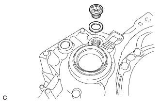
INSTALL WITH HEAD STRAIGHT SCREW PLUG (for Upper Side)
-
Clean and degrease the bolt holes.
Note
Do not allow any remaining seal packing to enter the hybrid vehicle transaxle assembly.
-
Using a 6 mm hexagon socket wrench, install a new with head straight screw plug to the hybrid vehicle transaxle assembly.
- Torque:
- 18 N*m { 180 kgf*cm, 13 ft.*lbf }
-
-
INSTALL WITH HEAD STRAIGHT SCREW PLUG (for RH Side)
-
Using a 10 mm hexagon socket wrench, install the with head straight screw and a new gasket to the hybrid vehicle transaxle assembly.
- Torque:
- 39 N*m { 400 kgf*cm, 29 ft.*lbf }
-
-
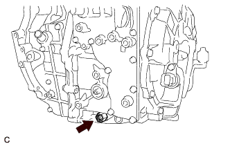
INSTALL DRAIN PLUG
-
Using a 10 mm hexagon socket wrench, install the drain plug and a new gasket to the hybrid vehicle transaxle assembly.
- Torque:
- 39 N*m { 400 kgf*cm, 29 ft.*lbf }
-
-
INSTALL FILLER PLUG
-
Using a 10 mm hexagon socket wrench, install the filler plug and a new gasket to the hybrid vehicle transaxle assembly.
- Torque:
- 39 N*m { 400 kgf*cm, 29 ft.*lbf }
-
-
INSTALL OIL PUMP DRIVE SHAFT
-
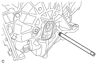
Install the oil pump drive shaft to the hybrid vehicle transaxle assembly.
-
-
INSTALL TRANSMISSION OIL PUMP COVER SUB-ASSEMBLY
-
Clean and degrease the bolt holes.
-
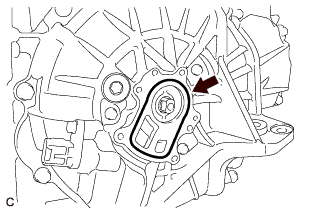
Coat a new O-ring with ATF and install it to the hybrid vehicle transaxle assembly.
Note
Be careful not to damage the O-ring.
-
Apply ATF to the transaxle oil pump drive rotor and oil pump driven rotor.
-
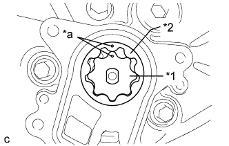
Text in Illustration *1 Transaxle Oil Pump Drive Rotor *2 Oil Pump Driven Rotor *a Matchmark Install the transaxle oil pump drive rotor and oil pump driven rotor to the hybrid vehicle transaxle assembly.
Note
-
Align the matchmarks on the transaxle oil pump drive rotor and the oil pump driven rotor.
-
If the transaxle oil pump drive rotor or oil pump driven rotor has been replaced, inspect the fluid pressure of the transmission oil pump cover sub-assembly.
-
-
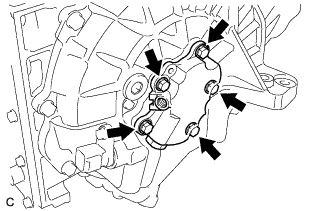
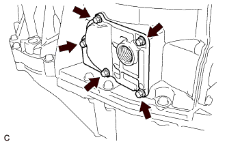
Install the transmission oil pump cover sub-assembly to the hybrid vehicle transaxle assembly with a new 5 bolts.
- Torque:
- 8.0 N*m { 82 kgf*cm, 71 in.*lbf }
Note
Do not pinch the O-ring.
-
Coat a new O-ring with ATF and install it to the fluid pump cover plug.
-
Install the fluid pump cover plug to the transmission oil pump cover sub-assembly.
- Torque:
- 8.0 N*m { 82 kgf*cm, 71 in.*lbf }
-
-
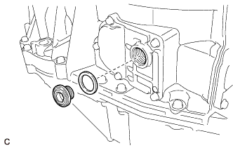
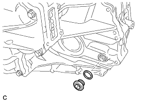
INSTALL TRANSAXLE BREATHER PLUG
-
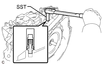
Using SST, install the transaxle breather plug to the hybrid vehicle transaxle assembly.
- SST
- 09810-38140
- Torque:
- 11 N*m { 115 kgf*cm, 8 ft.*lbf }
Note
Be careful not to damage the transaxle breather plug.
-
-
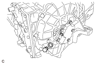
INSTALL SHIFT LEVER POSITION SENSOR
-
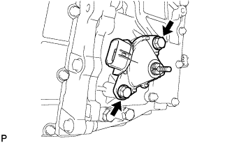
Temporarily install the shift lever position sensor to the hybrid vehicle transaxle assembly with 2 bolts.
Note
Do not reuse the shift lever position sensor if it has been dropped or subjected to a severe impact.
-
Install the lock nut and lock plate to the shift lever position sensor.
- Torque:
- 6.9 N*m { 70 kgf*cm, 61 in.*lbf }
-
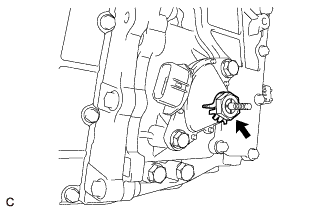
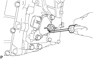
Temporarily install the control shaft lever to the shift lever position sensor.
-
Turn the lever clockwise until it stops, then turn it counterclockwise 2 notches.
-
Remove the control shaft lever from the shift lever position sensor.
-
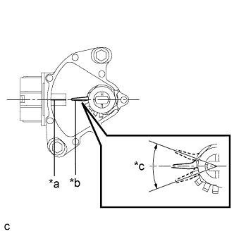
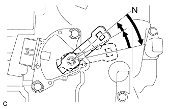
Text in Illustration *a Neutral Basic Line *b Protruding *c Range of Play Align the protruding part with the neutral basic line.
Note
There is play on the nut stopper side (protruding part). Align the center point of the range of play with the neutral basic line.
-
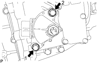
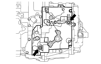
Tighten the 2 bolts in the order shown in the illustration.
- Torque:
- 13 N*m { 133 kgf*cm, 10 ft.*lbf }
-
Using a screwdriver, stake the nut with the lock plate.
-
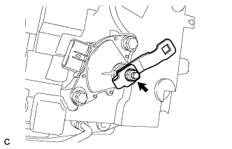
Install the control shaft lever, washer and nut to the shift lever position sensor.
- Torque:
- 13 N*m { 130 kgf*cm, 9 ft.*lbf }
-
-
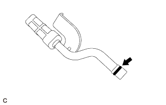
INSTALL OIL COOLER TUBE UNION
-
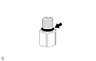
Coat a new O-ring with ATF and install it to the oil cooler tube union.
-
Install the oil cooler tube union to the hybrid vehicle transaxle assembly.
- Torque:
- 27 N*m { 275 kgf*cm, 20 ft.*lbf }
-
-
INSTALL NO. 2 AUTOMATIC TRANSMISSION CASE COVER
-
Install the No. 2 automatic transmission case cover to the hybrid vehicle transaxle assembly with 2 bolts and a new clip.
- Torque:
- 12 N*m { 120 kgf*cm, 9 ft.*lbf }
-
-
INSTALL INLET OIL COOLER TUBE SUB-ASSEMBLY
-
Text in Illustration *a Detent *b Rib Install the No. 1 oil cooler tube clamp to the hybrid vehicle transaxle assembly with the bolt.
- Torque:
- 8.2 N*m { 84 kgf*cm, 73 in.*lbf }
Note
Place the detent of the No. 1 oil cooler tube clamp to the rib.
-
Temporarily install the inlet oil cooler tube sub-assembly to the oil cooler tube union.
-
Text in Illustration *1 Oil Cooler Tube Union *2 Inlet Oil Cooler Tube Sub-assembly *3 No. 2 Oil Cooler Tube Clamp Install the No. 2 oil cooler tube clamp to the No. 1 oil cooler tube clamp with the bolt.
- Torque:
- 8.2 N*m { 84 kgf*cm, 73 in.*lbf }
Note
-
Check that the inlet oil cooler tube sub-assembly is securely installed to the No. 2 oil cooler tube clamp.
-
Make sure the inlet oil cooler tube sub-assembly is aligned with the oil cooler tube union to prevent the threads of the inlet oil cooler tube sub-assembly from being damaged.
-
Using a 17 mm union nut wrench, install the inlet oil cooler tube sub-assembly to the oil cooler tube union.
- Torque:
- 34 N*m { 350 kgf*cm, 25 ft.*lbf }
Note
Turn the inlet oil cooler tube sub-assembly while holding the oil cooler tube union.
-
-
INSPECT PARKING LOCK
Note
Confirm the safety of the working environment, then start the inspection.
Tech Tips
Perform this inspection on a level surface after installing the hybrid vehicle transaxle assembly to the vehicle.
-
Turn the power switch on (IG).*1
-
Depress the brake pedal and release the parking brake.*2
-
Check that park (P) is selected.*3
-
Push the vehicle forward by hand and check that it moves slightly and stops.*4
-
Move the shift lever to neutral (N).*5
-
Push the vehicle forward by hand and check that it moves.*6
-
Move the shift lever to park (P).*7
-
Push the vehicle forward by hand and check that it moves slightly and stops.*8
-
Perform steps *3 to *8 again, pushing the vehicle rearward this time.
-