HYBRID VEHICLE TRANSAXLE UNIT DISASSEMBLY

Note
-
Do not use gloves, cloths or papers that produce lint or dust.
-
Cover the removed parts with plastic bags to prevent entry of foreign matter.
-
Do not remove the power cable cover, generator cable, transaxle housing cover, rear transaxle case cover sub-assembly, rear planetary sun gear shaft snap ring or rear planetary sun gear.
-
The resolver is not adjustable. Do not remove the adjuster bolts.
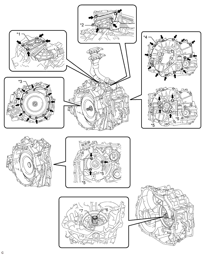
Text in Illustration *1 Power Cable Cover *2 Generator Cable *3 Transaxle Housing Cover *4 Rear Transaxle Case Cover Sub-assembly *5 Resolver Adjuster Bolt *6 Rear Planetary Sun Gear Shaft Snap Ring *7 Rear Planetary Sun Gear - -
-
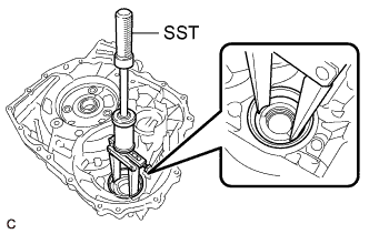
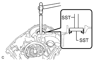
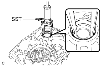
INSPECT INPUT SHAFT ASSEMBLY END PLAY
-
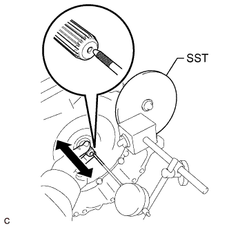
Using SST and a dial indicator, measure the input shaft assembly end play.
- SST
- 09951-01600
Standard End Play 0.1 to 0.2 mm (0.00394 to 0.00787 in.) If the value is not as specified, replace the planetary sun gear snap ring with one of the correct thickness.
-
-
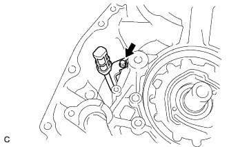
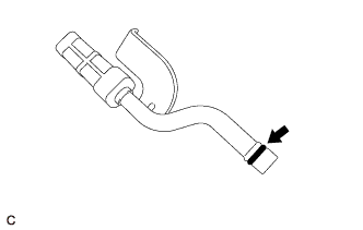
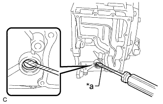
REMOVE INLET OIL COOLER TUBE SUB-ASSEMBLY
-
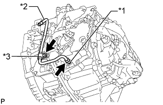
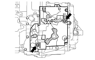
Text in Illustration *1 Oil Cooler Tube Union *2 Inlet Oil Cooler Tube Sub-assembly *3 No. 2 Oil Cooler Tube Clamp Using a 17 mm union nut wrench, separate the inlet oil cooler tube sub-assembly from the oil cooler tube union.
Note
Turn the inlet oil cooler tube sub-assembly while holding the oil cooler tube union.
-
Remove the bolt, No. 2 oil cooler tube clamp and inlet oil cooler tube sub-assembly from the No. 1 oil cooler tube clamp.
-
Remove the bolt and No. 1 oil cooler tube clamp from the hybrid vehicle transaxle assembly.
-
-
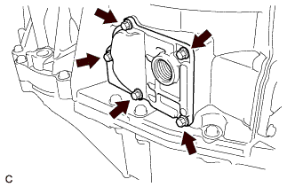
REMOVE NO. 2 AUTOMATIC TRANSMISSION CASE COVER
-
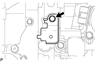
Remove the 2 bolts, clip and No. 2 automatic transmission case cover from the hybrid vehicle transaxle assembly.
-
-
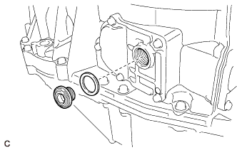
REMOVE OIL COOLER TUBE UNION
-
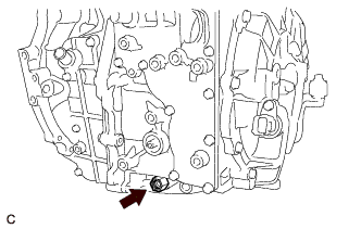
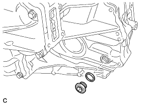
Remove the oil cooler tube union from the hybrid vehicle transaxle assembly.
-
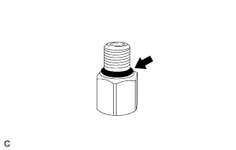
Remove the O-ring from the oil cooler tube union.
-
-
REMOVE SHIFT LEVER POSITION SENSOR
-
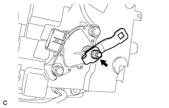
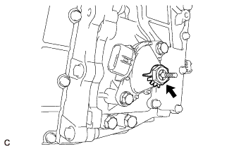
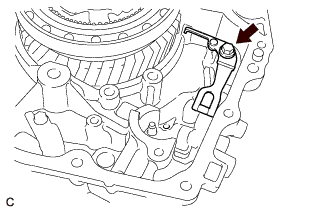
Remove the nut, washer and control shaft lever from the shift lever position sensor.
-
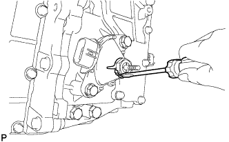
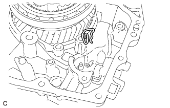
Using a screwdriver, pry out the lock plate.
-
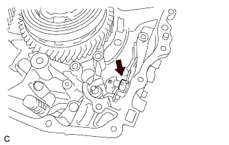
Remove the lock nut and lock plate from the shift lever position sensor.
-
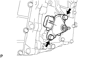
Remove the 2 bolts and pull out the shift lever position sensor from the hybrid vehicle transaxle assembly.
-
-
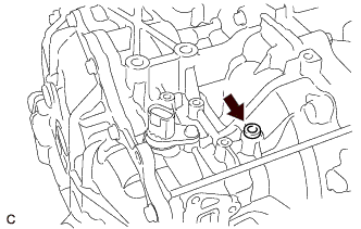
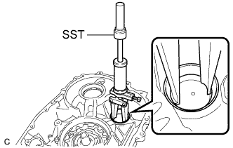
REMOVE TRANSAXLE BREATHER PLUG
-
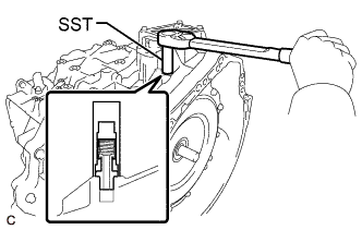
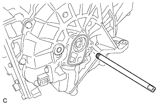
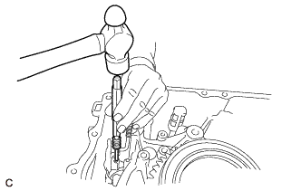
Using SST, remove the transaxle breather plug from the hybrid vehicle transaxle assembly.
- SST
- 09810-38140
Note
Be careful not to damage the transaxle breather plug.
-
-
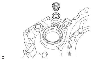
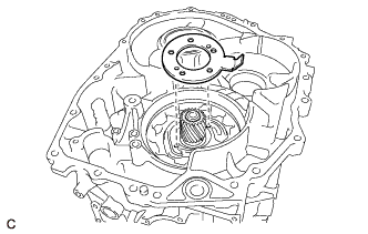
REMOVE TRANSMISSION OIL PUMP COVER SUB-ASSEMBLY
-
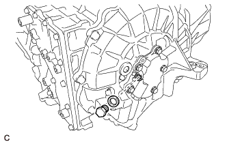
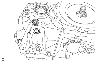
Remove the fluid pump cover plug and O-ring from the transmission oil pump cover sub-assembly.
-
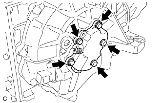
Remove the 5 bolts and transmission oil pump cover sub-assembly from the hybrid vehicle transaxle assembly.
Note
Do not drop the transaxle oil pump drive rotor or oil pump driven rotor.
-
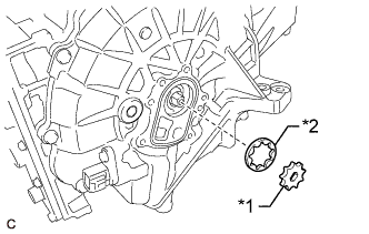
Text in Illustration *1 Transaxle Oil Pump Drive Rotor *2 Oil Pump Driven Rotor Remove the transaxle oil pump drive rotor and oil pump driven rotor from the hybrid vehicle transaxle assembly.
-
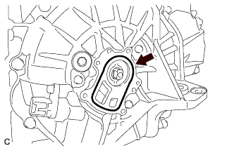
Remove the O-ring from the hybrid vehicle transaxle assembly.
-
-
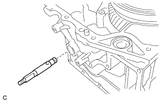
REMOVE OIL PUMP DRIVE SHAFT
-
Remove the oil pump drive shaft from the hybrid vehicle transaxle assembly.
-
-
SECURE HYBRID VEHICLE TRANSAXLE ASSEMBLY
-
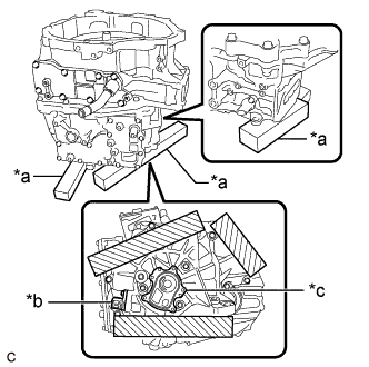
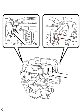
Text in Illustration *a Wooden Block *b Resolver Sensor Connector *c Installation area of the transmission oil pump cover sub-assembly 
Wooden block placement position Place wooden blocks under the hybrid vehicle transaxle assembly.
Note
Do not place the wooden blocks under the installation area of the transmission oil pump cover sub-assembly or resolver sensor connector.
-
-
REMOVE FILLER PLUG
-
Using a 10 mm hexagon socket wrench, remove the filler plug and gasket from the hybrid vehicle transaxle assembly.
-
-
REMOVE DRAIN PLUG
-
Using a 10 mm hexagon socket wrench, remove the drain plug and gasket from the hybrid vehicle transaxle assembly.
-
-
REMOVE WITH HEAD STRAIGHT SCREW PLUG (for RH Side)
-
Using a 10 mm hexagon socket wrench, remove the with head straight screw plug and gasket from the hybrid vehicle transaxle assembly.
-
-
REMOVE WITH HEAD STRAIGHT SCREW PLUG (for Upper Side)
-
Using a 6 mm hexagon socket wrench, remove the with head straight screw plug from the hybrid vehicle transaxle assembly.
Note
Do not allow any remaining seal packing to enter the hybrid vehicle transaxle assembly.
-
-
REMOVE NO. 2 MOTOR WATER JACKET COVER ASSEMBLY
-
Using a 10 mm hexagon socket wrench, remove the drain plug and gasket from the No. 2 motor water jacket cover assembly.
-
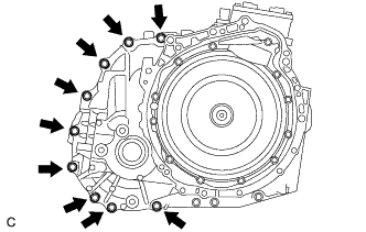
Remove the 5 bolts and No. 2 motor water jacket cover assembly from the hybrid vehicle transaxle assembly.
-
-
REMOVE NO. 1 MOTOR WATER JACKET COVER ASSEMBLY
-
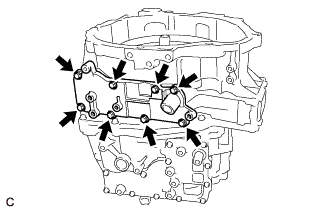
Remove the 8 bolts and No. 1 motor water jacket cover assembly from the hybrid vehicle transaxle assembly.
-
-
REMOVE MOTOR WATER JACKET COVER ASSEMBLY
-
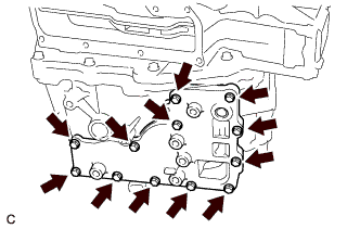
Remove the 12 bolts and motor water jacket cover assembly from the hybrid vehicle transaxle assembly.
-
-
REMOVE HYBRID VEHICLE GENERATOR ASSEMBLY
-
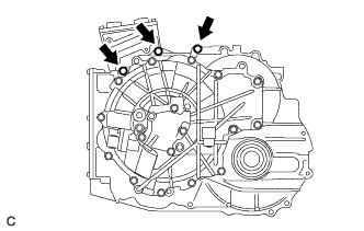
Install the No. 1 engine hanger and No. 2 engine hanger with the 2 bolts and washer as shown in the illustration.
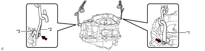
Text in Illustration *1 No. 1 Engine Hanger *2 No. 2 Engine Hanger *3 Washer - - - Torque:
- 43 N*m { 438 kgf*cm, 32 ft.*lbf }
Part Name Part No. No. 1 Engine Hanger 12281-37050 No. 2 Engine Hanger 12282-37040 Bolt 91552-81050 Tech Tips
When installing the No. 2 engine hanger, use a washer with an appropriate thickness so that the No. 2 engine hanger will not interfere with the installation surface of the hybrid vehicle generator assembly.
-
Remove the 9 bolts from the hybrid vehicle generator assembly.
-
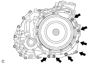
Remove the 7 bolts from the hybrid vehicle generator assembly.
-
Remove the 3 bolts from the hybrid vehicle motor assembly.
-
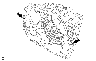
While lifting the hybrid vehicle generator assembly with a chain, tap the areas shown in the illustration with a plastic hammer and separate the hybrid vehicle generator assembly from the hybrid vehicle motor assembly.
-
While lifting the hybrid vehicle generator assembly with a chain, remove it from the hybrid vehicle motor assembly.
Note
-
Lift the hybrid vehicle generator assembly straight up.
-
If the hybrid vehicle generator assembly is tilted, return it to the original position before removing.
-
-
Remove the 2 bolts, washer, No. 1 engine hanger and No. 2 engine hanger from the hybrid vehicle generator assembly.
-
-
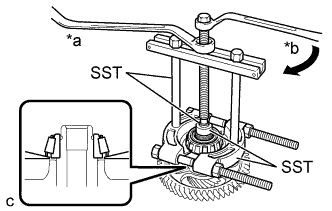
REMOVE TAPERED ROLLER BEARING (OUTER RACE) (for RH Side)
-
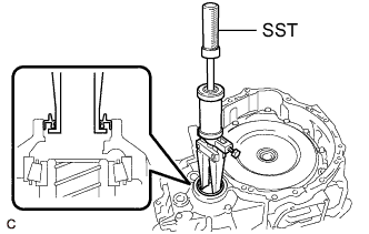
Using SST, remove the tapered roller bearing (outer race) and differential case RH shim from the hybrid vehicle generator assembly.
- SST
- 09308-36010
Note
Be careful not to damage the hybrid vehicle generator assembly.
-
-
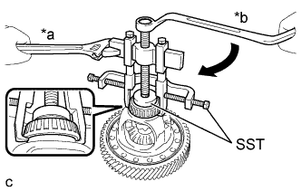
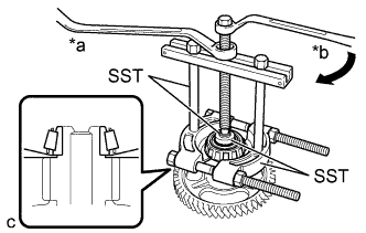
REMOVE TAPERED ROLLER BEARING (OUTER RACE) (for RH Side)
-
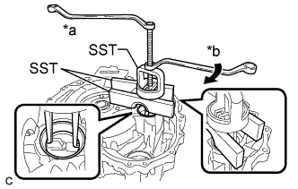
Text in Illustration *a Hold *b Turn Using SST, remove the tapered roller bearing (outer race) and counter driven gear shim from the hybrid vehicle generator assembly.
- SST
- 09527-20011
- 09527-21011
- 09612-65014 ( 09612-01030 )
Note
Be careful not to damage the hybrid vehicle generator assembly.
-
-
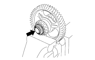
REMOVE HYBRID VEHICLE TRANSAXLE ASSEMBLY TYPE T OIL SEAL (for RH Side)
-
Using SST, remove the hybrid vehicle transaxle assembly type T oil seal from the hybrid vehicle generator assembly.
- SST
- 09308-36010
-
-
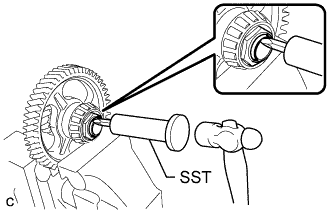
REMOVE INPUT SHAFT TYPE T OIL SEAL
-
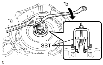
Text in Illustration *a Hold *b Turn Using SST, remove the input shaft type T oil seal from the hybrid vehicle generator assembly.
- SST
- 09310-36021
- 09502-24010
Note
-
Be careful not to damage the hybrid vehicle generator assembly.
-
When removing the hybrid vehicle generator assembly, be sure to replace the input shaft type T oil seal.
-
-
REMOVE NO. 2 TRANSMISSION OIL STRAINER
-
Remove the bolt and No. 2 transmission oil strainer from the hybrid vehicle motor assembly.
-

Remove the O-ring from the No. 2 transmission oil strainer.
-
-
REMOVE PARKING LOCK PAWL
-
Remove the parking lock pawl and parking lock pawl shaft from the hybrid vehicle motor assembly.
-
-
REMOVE PAWL STOPPER PLATE
-
Remove the 2 bolts and pawl stopper plate from the hybrid vehicle motor assembly.
-
-
REMOVE TORSION SPRING
-
Remove the parking lock pawl shaft and torsion spring from the hybrid vehicle motor assembly.
-
-
REMOVE PARKING LOCK SLEEVE
-
Remove the parking lock sleeve from the hybrid vehicle motor assembly.
-
-
REMOVE MANUAL DETENT SPRING SUB-ASSEMBLY
-
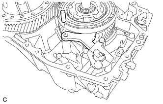
Remove the bolt and manual detent spring sub-assembly from the hybrid vehicle motor assembly.
-
-
REMOVE RETAINER SPRING
-
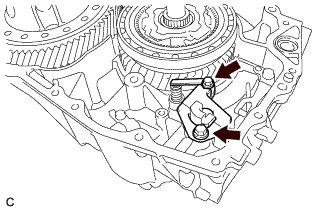
Remove the retainer spring from the hybrid vehicle motor assembly and No. 1 parking lock shaft.
-
-
REMOVE NO. 1 PARKING LOCK SHAFT
-
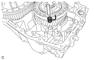
Using a hammer and a screwdriver, unstake the spacer.
-
Align the cutout of the spacer with the slotted spring pin hole, and then using a 5 mm pin punch and a hammer, drive out the slotted spring pin from the No. 1 parking lock shaft.
-
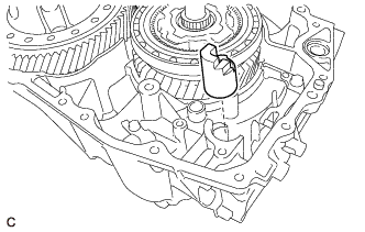
Remove the No. 1 parking lock shaft from the hybrid vehicle motor assembly.
-
-
REMOVE PARKING LOCK ROD SUB-ASSEMBLY
-
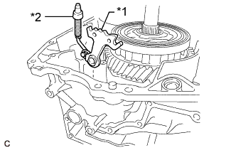
Text in Illustration *1 No. 1 Parking Lock Lever Sub-assembly *2 Parking Lock Rod Sub-assembly Remove the No. 1 parking lock lever sub-assembly and parking lock rod sub-assembly from the hybrid vehicle motor assembly.
-
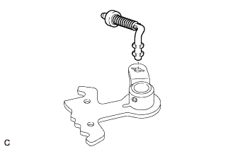
Remove the parking lock rod sub-assembly from the No. 1 parking lock lever sub-assembly.
-
-
REMOVE NO. 1 TRANSMISSION MAGNET
-
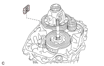
Remove the No. 1 transmission magnet from the hybrid vehicle motor assembly.
-
-
REMOVE INPUT SHAFT ASSEMBLY
-
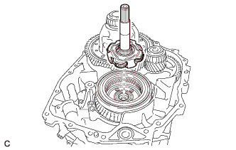
Remove the input shaft assembly from the counter drive gear sub-assembly.
-
-
REMOVE PLANETARY SUN GEAR
-
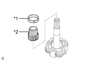
Text in Illustration *1 Planetary Sun Gear Snap Ring *2 Planetary Sun Gear Remove the planetary sun gear snap ring and planetary sun gear from the input shaft assembly.
-
-
REMOVE THRUST NEEDLE ROLLER BEARING
-
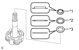
Text in Illustration *1 Thrust Bearing Race *2 Thrust Needle Roller Bearing *3 No. 1 Thrust Bearing Race Remove the thrust bearing race, thrust needle roller bearing and No. 1 thrust bearing race from the input shaft assembly.
Tech Tips
The No. 1 thrust bearing race may be attached to the input shaft assembly.
-
-
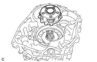
REMOVE DIFFERENTIAL CASE SUB-ASSEMBLY
-
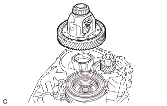
Remove the differential case sub-assembly from the hybrid vehicle motor assembly.
-
-
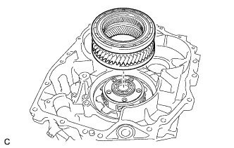
REMOVE COUNTER DRIVEN GEAR SUB-ASSEMBLY
-
Remove the counter driven gear sub-assembly from the hybrid vehicle motor assembly.
-
-
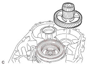
REMOVE COUNTER DRIVE GEAR SUB-ASSEMBLY
-
Remove the counter drive gear sub-assembly from the No. 1 rear planetary gear assembly.
-
-
REMOVE NO. 1 REAR PLANETARY GEAR ASSEMBLY
-
Remove the No. 1 rear planetary gear assembly from the rear planetary sun gear.
-
-
INSPECT NO. 1 REAR PLANETARY GEAR ASSEMBLY
-
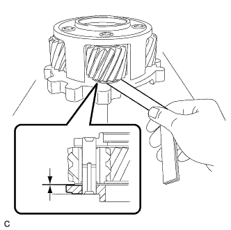
Using a feeler gauge, measure the clearance between the No. 1 rear planetary gear assembly and the pinion gear.
Standard Clearance 0.2 to 0.8 mm (0.00787 to 0.0315 in.) If the value is not as specified, replace the No. 1 rear planetary gear assembly.
-
-
REMOVE PLANETARY OIL RECEIVER
-
Remove the planetary oil receiver from the hybrid vehicle motor assembly.
-
-
REMOVE TRANSMISSION OIL STRAINER
-
Remove the bolt and transmission oil strainer from the hybrid vehicle motor assembly.
-
Remove the O-ring from the transmission oil strainer.
-
-
REMOVE HYBRID VEHICLE TRANSAXLE ASSEMBLY TYPE T OIL SEAL (for LH Side)
-
Using SST and a hammer, remove the hybrid vehicle transaxle assembly type T oil seal from the hybrid vehicle motor assembly.
- SST
- 09950-60010 ( 09951-00750 )
- 09950-70010 ( 09951-07200 )
-
-
REMOVE TAPERED ROLLER BEARING (OUTER RACE) (for LH Side)
-
Using SST, remove the tapered roller bearing (outer race) from the hybrid vehicle motor assembly.
- SST
- 09308-36010
Note
Be careful not to damage the hybrid vehicle motor assembly.
-
-
REMOVE TAPERED ROLLER BEARING (OUTER RACE) (for LH Side)
-
Using SST, remove the tapered roller bearing (outer race) from the hybrid vehicle motor assembly.
- SST
- 09308-36010
Note
Be careful not to damage the hybrid vehicle motor assembly.
-
-
REMOVE PARKING LOCK SHAFT TYPE T OIL SEAL
-
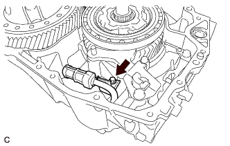
Text in Illustration *a Protective Tape Using a screwdriver with its tip wrapped with protective tape, remove the parking lock shaft type T oil seal from the hybrid vehicle motor assembly.
Note
Be careful not to damage the hybrid vehicle motor assembly.
-
-
REMOVE TAPERED ROLLER BEARING (INNER RACE) (for LH Side)
-
Text in Illustration *a Hold *b Turn Using SST, remove the tapered roller bearing (inner race) from the differential case sub-assembly.
- SST
- 09950-40011 ( 09951-04010, 09952-04010, 09953-04030, 09954-04010, 09955-04061, 09957-04010, 09958-04011 )
- 09950-60010 ( 09951-00460 )
-
-
REMOVE TAPERED ROLLER BEARING (INNER RACE) (for RH Side)
-
Text in Illustration *a Hold *b Turn Using SST, remove the tapered roller bearing (inner race) from the differential case sub-assembly.
- SST
- 09950-40011 ( 09951-04010, 09952-04010, 09953-04030, 09954-04010, 09955-04061, 09957-04010, 09958-04011 )
- 09950-60010 ( 09951-00460 )
-
-
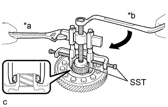
REMOVE LOCK NUT
-
Secure the counter driven gear sub-assembly in a vise using aluminum plates.
Note
Be careful not to damage the counter driven gear sub-assembly in the vise.
-
Using SST and a hammer, loosen the staked part of the lock nut.
- SST
- 09930-00010
-
Using a 41 mm deep socket wrench, remove the lock nut from the counter driven gear sub-assembly.
-
-
REMOVE TAPERED ROLLER BEARING (INNER RACE) (for LH Side)
-
Text in Illustration *a Hold *b Turn Using SST, remove the tapered roller bearing (inner race) from the counter driven gear sub-assembly.
- SST
- 09950-00020
- 09950-00030
- 09950-40011 ( 09957-04010 )
- 09950-60010 ( 09951-00280 )
-
-
REMOVE TAPERED ROLLER BEARING (INNER RACE) (for RH Side)
-
Text in Illustration *a Hold *b Turn Using SST, remove the tapered roller bearing (inner race) from the counter driven gear sub-assembly.
- SST
- 09950-00020
- 09950-00030
- 09950-40011 ( 09957-04010 )
- 09950-60010 ( 09951-00320 )
-
-
REMOVE STRAIGHT PIN
-
Remove the 2 straight pins from the hybrid vehicle motor assembly.
Note
Be careful not to damage the hybrid vehicle motor assembly.
-