DYNAMIC RADAR CRUISE CONTROL SYSTEM Wiper Signal Circuit
DESCRIPTION
When the driving support ECU detects that the wipers are operating at high speed, the dynamic radar cruise control system will be canceled.
WIRING DIAGRAM
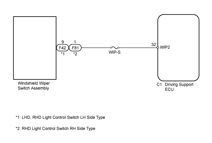
INSPECTION PROCEDURE
Note
Inspect the fuses for circuits related to this system before performing the following inspection procedure.
PROCEDURE
-
INSPECT DRIVING SUPPORT ECU
-
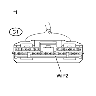
Text in Illustration *1 Front view of wire harness connector
(to Driving Support ECU)
Disconnect the driving support ECU connector.
-
Turn the power switch on (IG).
-
Set the windshield wiper switch assembly to the HI position.
-
Measure the voltage according to the value(s) in the table below.
Standard Voltage Tester Connection Condition Specified Condition C1-32 (WIP2) - Body ground Power switch on (IG)
Windshield wiper switch assembly in HI position
11 to 14 V -
Reconnect the driving support ECU connector.
NG 
CHECK HARNESS AND CONNECTOR (DRIVING SUPPORT CONTROL ECU - WINDSHIELD WIPER SWITCH) Click here
OK 
PROCEED TO NEXT SUSPECTED AREA SHOWN IN PROBLEM SYMPTOMS TABLE Click here
-
-
CHECK HARNESS AND CONNECTOR (DRIVING SUPPORT CONTROL ECU - WINDSHIELD WIPER SWITCH)
-
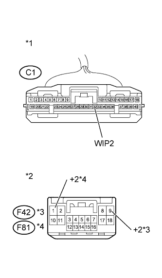
Text in Illustration *1 Front view of wire harness connector
(to Driving Support ECU)
*2 Front view of wire harness connector
(to Windshield Wiper Switch Assembly)
*3 for LHD, RHD Light Control Switch LH Side Type *4 for RHD Light Control Switch RH Side Type Disconnect the driving support ECU connector.
-
Disconnect the windshield wiper switch assembly connector.
-
Measure the resistance according to the value(s) in the table below.
Standard Resistance (Check for Open) for LHD, RHD Light Control Switch LH Side Type Tester Connection Condition Specified Condition C1-32 (WIP2) - F42-9 (+2) Always Below 1 Ω for RHD Light Control Switch RH Side Type Tester Connection Condition Specified Condition C1-32 (WIP2) - F81-1 (+2) Always Below 1 Ω Standard Resistance (Check for Short) for LHD, RHD Light Control Switch LH Side Type Tester Connection Condition Specified Condition C1-32 (WIP2) or F42-9 (+2) - Body ground Always 10 kΩ or higher for RHD Light Control Switch RH Side Type Tester Connection Condition Specified Condition C1-32 (WIP2) or F81-1 (+2) - Body ground Always 10 kΩ or higher -
Reconnect the driving support ECU connector.
-
Reconnect the windshield wiper switch assembly connector.
NG 
REPAIR OR REPLACE HARNESS OR CONNECTOR (DRIVING SUPPORT CONTROL ECU - WINDSHIELD WIPER SWITCH)
OK
GO TO WIPER AND WASHER SYSTEM Click here
-