DYNAMIC RADAR CRUISE CONTROL SYSTEM Distance Control Switch Circuit
DESCRIPTION
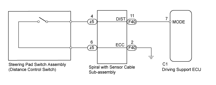
The distance control switch sets vehicle-to-vehicle distance control mode distance. The distance control switch is installed in the steering pad switch assembly. The vehicle-to-vehicle distance set value can be changed by operating the steering pad switch assembly (distance control switch) while the dynamic radar cruise control system is operating.
WIRING DIAGRAM
INSPECTION PROCEDURE
PROCEDURE
-
READ VALUE USING INTELLIGENT TESTER (DISTANCE CONTROL SWITCH)
-
Connect the intelligent tester to the DLC3.
-
Turn the power switch on (IG).
-
Turn the tester on.
-
Enter the following menus: Powertrain / Radar Cruise / Data List / Distance Control Switch.
-
Check the Data List proper functioning of the distance control switch.
Radar Cruise Tester Display Measurement Item/Range Normal Condition Diagnostic Note Distance Control Switch Distance control switch signal/ON or OFF ON: Distance control switch on
OFF: Distance control switch off
- OK When the distance control switch is operated, the display changes as shown above.
NG 
INSPECT STEERING PAD SWITCH ASSEMBLY Click here
OK 
PROCEED TO NEXT SUSPECTED AREA SHOWN IN PROBLEM SYMPTOMS TABLE Click here
-
-
INSPECT STEERING PAD SWITCH ASSEMBLY
-
Disconnect the z5 connector from the spiral with sensor cable sub-assembly.
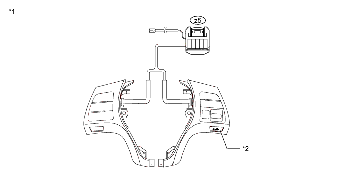
Text in Illustration *1 Component without harness connected
(Steering Pad Switch Assembly)
*2 Distance Control Switch -
Measure the resistance according to the value(s) in the table below.
Standard Resistance Tester Connection Switch Condition Specified Condition z5-4 - z5-6 Distance control switch ON Below 2.5 Ω z5-4 - z5-6 Distance control switch OFF 1 MΩ or higher -
Reconnect the z5 connector to the spiral with sensor cable sub-assembly.
NG 
REPLACE STEERING PAD SWITCH ASSEMBLY Click here
OK 
-
-
INSPECT SPIRAL WITH SENSOR CABLE SUB-ASSEMBLY
Note
The spiral with sensor cable sub-assembly is an important part of the SRS airbag system. Incorrect removal or installation of the spiral with sensor cable sub-assembly may cause airbag deployment. Be sure to read the page shown in the brackets.
-
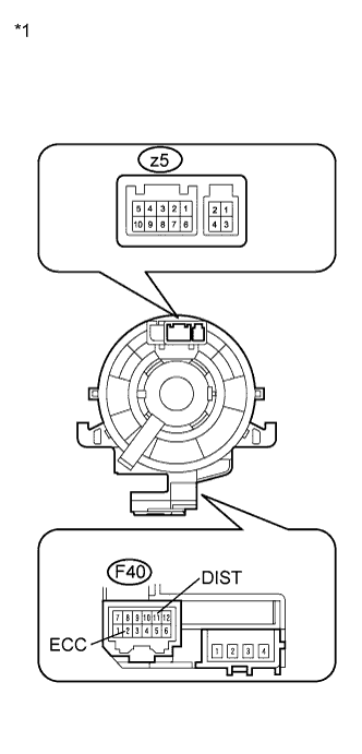
Text in Illustration *1 Component without harness connected
(Spiral with Sensor Cable Sub-assembly)
Remove the spiral with sensor cable sub-assembly.
-
Measure the resistance according to the value(s) in the table below.
Standard Resistance Tester Connection Condition Specified Condition z5-4 - F40-11 (DIST) The spiral with sensor cable sub-assembly position is center Below 1 Ω The spiral with sensor cable sub-assembly position is 2.5 rotations to the left The spiral with sensor cable sub-assembly position is 2.5 rotations to the right z5-6 - F40-2 (ECC) The spiral with sensor cable sub-assembly position is center Below 1 Ω The spiral with sensor cable sub-assembly position is 2.5 rotations to the left The spiral with sensor cable sub-assembly position is 2.5 rotations to the right Tech Tips
The spiral with sensor cable sub-assembly makes a maximum of approximately 5 rotations.
-
Reinstall the spiral with sensor cable sub-assembly.
NG
REPLACE SPIRAL WITH SENSOR CABLE SUB-ASSEMBLY Click here
OK
-
-
CHECK HARNESS AND CONNECTOR (SPIRAL WITH SENSOR CABLE SUB-ASSEMBLY - DRIVING SUPPORT ECU)
-
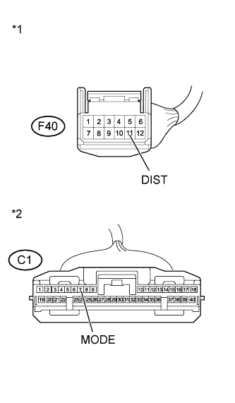
Text in Illustration *1 Front view of wire harness connector
(to Spiral with Sensor Cable Sub-assembly)
*2 Front view of wire harness connector
(to Driving Support ECU)
Disconnect the driving support ECU connector.
-
Disconnect the spiral with sensor cable sub-assembly connector.
-
Measure the resistance according to the value(s) in the table below.
Standard Resistance (Check for Open) Tester Connection Condition Specified Condition C1-7 (MODE) - F40-11 (DIST) Always Below 1 Ω Standard Resistance (Check for Short) Tester Connection Condition Specified Condition C1-7 (MODE) or F40-11 (DIST) - Body ground Always Below 1 Ω -
Reconnect the driving support ECU connector.
-
Reconnect the spiral with sensor cable sub-assembly connector.
NG
REPAIR OR REPLACE HARNESS OR CONNECTOR (SPIRAL WITH SENSOR CABLE SUB-ASSEMBLY - DRIVING SUPPORT ECU)
OK
-
-
CHECK HARNESS AND CONNECTOR (SPIRAL WITH SENSOR CABLE SUB-ASSEMBLY - BODY GROUND)
-
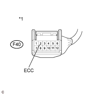
Text in Illustration *1 Front view of wire harness connector
(to Spiral with Sensor Cable Sub-assembly)
Disconnect the spiral with sensor cable sub-assembly connector.
-
Measure the resistance according to the value(s) in the table below.
Standard Resistance (Check for Open) Tester Connection Condition Specified Condition F40-2 (ECC) - Body ground Always Below 1 Ω -
Reconnect the spiral with sensor cable sub-assembly connector.
NG
REPAIR OR REPLACE HARNESS OR CONNECTOR (SPIRAL WITH SENSOR CABLE SUB-ASSEMBLY - BODY GROUND)
OK
REPLACE DRIVING SUPPORT ECU Click here
-