POWER SWITCH REMOVAL

-
PRECAUTION (w/ Navigation System for HDD)
Note
After the power switch is turned off, the display and navigation module display (HDD navigation system) records various types of memory and settings. As a result, after turning the power switch off, make sure to wait for the time specified in the following table before disconnecting the cable from the negative (-) battery terminal.
Waiting Time before Disconnecting Cable from Negative (-) Battery Terminal Specification Waiting Time w/o Telematics transceiver 60 sec. w/ Telematics transceiver 120 sec. -
REMOVE REAR DECK FLOOR BOX
-

Remove the 3 clips and the rear deck floor box.
-
-
DISCONNECT CABLE FROM NEGATIVE BATTERY TERMINAL
CAUTION:
Wait at least 90 seconds after disconnecting the cable from the negative (-) battery terminal to disable the SRS system.
Note
When disconnecting the cable, some systems need to be initialized after the cable is reconnected Click here.
-
REMOVE FRONT DOOR SCUFF PLATE LH (for LHD)
-
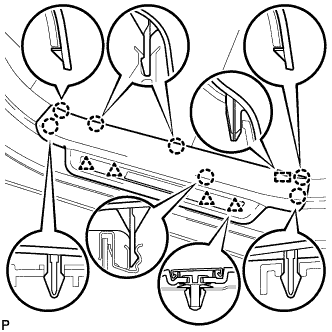
Disengage the 7 claws, 4 clips and guide, and remove the front door scuff plate LH.
Tech Tips
A part of the clip remains on the vehicle side.
-
w/ Illumination:
-
Disconnect the connector.
-
-
-
REMOVE FRONT DOOR SCUFF PLATE RH (for RHD)
Tech Tips
Use the same procedure for the RH side and LH side Click here.
-
REMOVE COWL SIDE TRIM SUB-ASSEMBLY LH (for LHD)
-
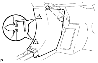
Remove the clip.
-
Disengage the 2 clips and remove the cowl side trim sub-assembly LH.
-
-
REMOVE COWL SIDE TRIM SUB-ASSEMBLY RH (for RHD)
Tech Tips
Use the same procedure for the RH side and LH side Click here.
-
REMOVE INSTRUMENT PANEL GARNISH LH (for LHD)
-
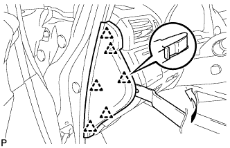
Using moulding remover B, disengage the 6 clips and remove the instrument panel garnish LH as shown in the illustration.
-
-
REMOVE INSTRUMENT PANEL GARNISH RH (for RHD)
-
REMOVE NO. 1 SWITCH HOLE BASE
-
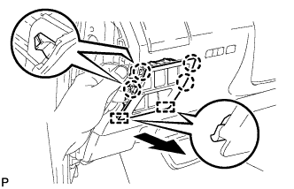
Push the No. 1 switch hole base in the direction indicated by the arrow to disengage the 4 claws and 2 guides.
-
Disconnect each connector and remove the No. 1 switch hole base.
-
-
REMOVE LOWER INSTRUMENT PANEL FINISH PANEL SUB-ASSEMBLY
-
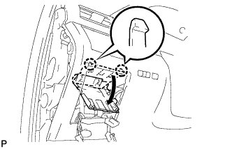
Disengage the 2 claws and open the cover as shown in the illustration.
-

Remove the 2 screws <D>.
-
Disengage the 8 clips and 2 guides.
-
Disconnect each connector and remove the lower instrument panel finish panel sub-assembly.
-
-
REMOVE POWER SWITCH
-
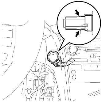
Detach the 2 claws and remove the power switch.
-
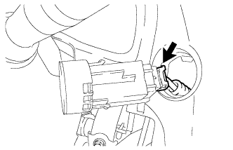
Disconnect the power switch connector.
-