OIL PUMP INSTALLATION

-
INSTALL TIMING CHAIN COVER OIL SEAL
-
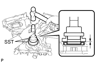
Using SST, tap in a new oil seal until its surface is flush with the timing chain case edge.
- SST
- 09223-22010
- 09506-35010
Note
-
Keep the lip free from foreign matter.
-
Do not tap on the oil seal at an angle.
-
Make sure that the oil seal edge does not stick out of the timing chain case.
Tech Tips
Tap in the oil seal so that it is positioned within 1.0 mm from the edge of the timing chain case.
-
Apply a light coat of MP grease to the timing chain cover oil seal lip.
-
-
INSTALL TIMING CHAIN COVER SUB-ASSEMBLY
-
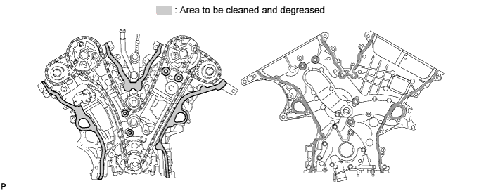
Remove any old packing material remaining on the sealing surfaces before applying seal packing.
-
Clean and degrease the contact surfaces of the timing chain cover, cylinder head and cylinder block, and confirm that no oil, moisture or other foreign matter remains on the surfaces.
-
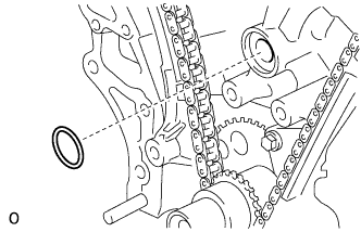
Install a new gasket.
-
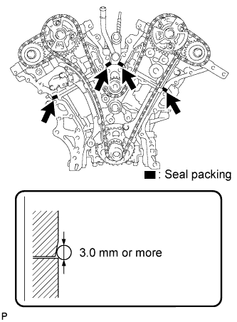
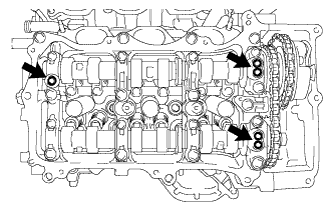
Apply seal packing in a continuous line to the engine unit as shown in the following illustration.
Seal packing Toyota Genuine Seal Packing Black, Three Bond 1207B or equivalent Seal diameter 3.0 mm (0.118 in.) Note
-
When the contact surfaces are wet, wipe them with an oil-free cloth before applying seal packing.
-
Install the chain cover within 3 minutes and tighten the bolts within 10 minutes after applying seal packing.
-
Do not add engine oil for at least 2 hours after installing the chain cover.
-
Do not start the engine for at least 2 hours after installing the chain cover.
-
-
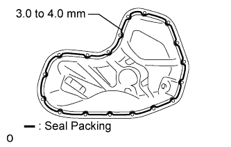
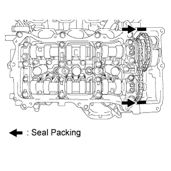
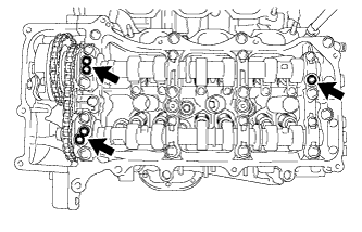
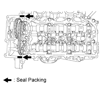
Apply seal packing in a line to the timing chain cover as shown in the following illustration.
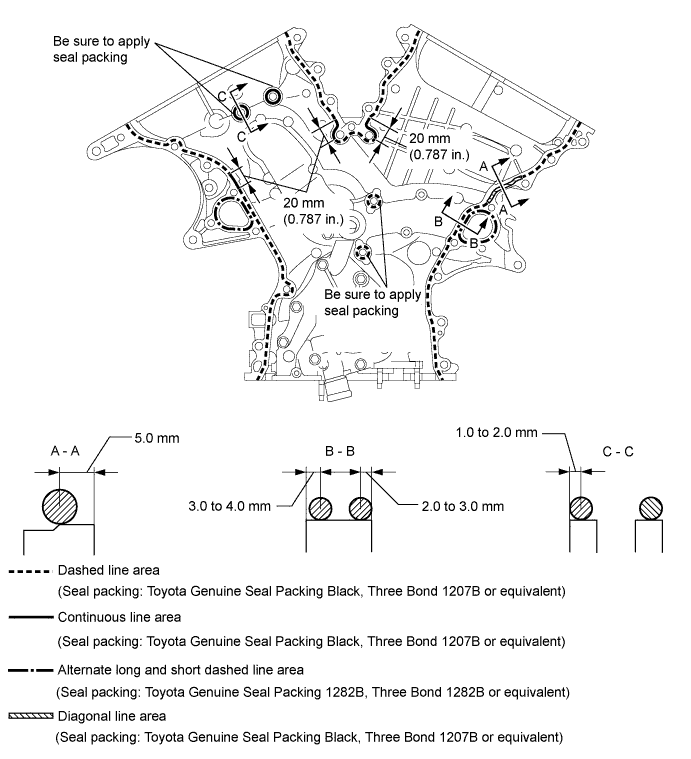
Seal packing Toyota Genuine Seal Packing Black, Three Bond 1207B or equivalent Toyota Genuine Seal Packing 1282B, Three Bond 1282B or equivalent Note
-
If the contact surfaces are wet, wipe them with an oil-free cloth before applying seal packing.
-
Install the chain cover within 3 minutes and tighten the bolts within 10 minutes after applying seal packing.
-
Do not add the engine oil for at least 2 hours after installing.
-
Do not start the engine for at least 2 hours after installing.
Seal Packing Application Chart Area Seal Packing Diameter Application Position from Inside Seal Line Continuous Line Area 4.5 mm (0.177 in.) or more 3.0 to 4.0 mm (0.118 to 0.158 in.) Alternate Long and Dashed Line Area 3.5 mm (0.138 in.) or more 2.0 to 3.0 mm (0.0787 to 0.118 in.) Dashed Line Area 3.5 mm (0.138 in.) or more 3.0 to 4.0 mm (0.118 to 0.158 in.) Diagonal Line Area 6.0 mm (0.236 in.) or more 5.0 mm (0.197 in.) -
-
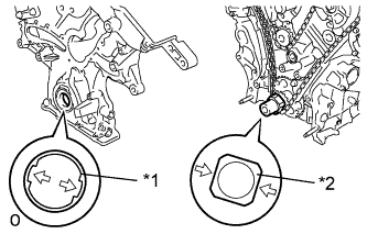
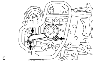
Text in Illustration *1 Drive Rotor Spline *2 Crankshaft Align the oil pump's drive rotor spline and the crankshaft as shown in the illustration. Install the chain cover to the crankshaft.
-
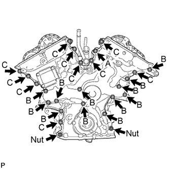
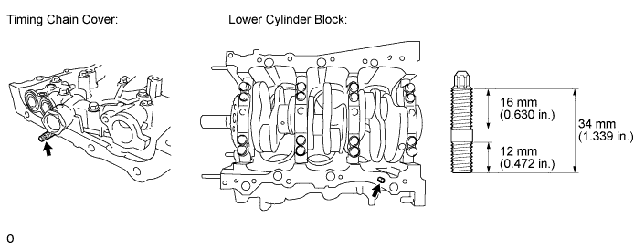
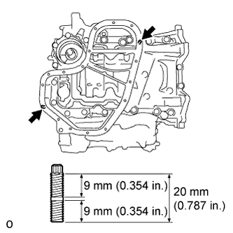
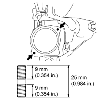
Temporarily tighten the timing chain cover with the 23 bolts and 2 nuts.
Bolt Length Item Length Bolt A 40 mm (1.57 in.) Bolt B 55 mm (2.17 in.) Bolt C 25 mm (0.984 in.) Note
Make sure that there is no oil on the bolt and nut threads.
-
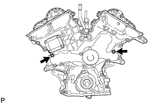
Fully tighten the 2 bolts.
- Torque:
- 21 N*m { 214 kgf*cm, 15 ft.*lbf }
-
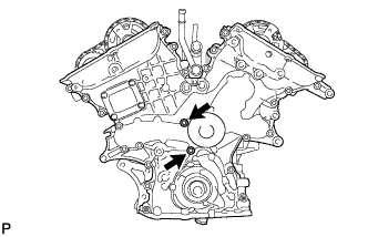
Fully tighten the 2 bolts.
- Torque:
- 21 N*m { 214 kgf*cm, 15 ft.*lbf }
-
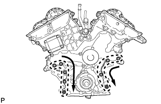
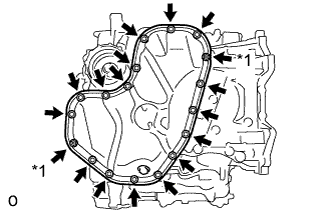
Fully tighten the 7 bolts and 2 nuts.
- Torque:
- 21 N*m { 214 kgf*cm, 15 ft.*lbf }
Tech Tips
First tighten the upper bolts and nuts followed by the lower bolts and nuts as shown in the illustration.
-
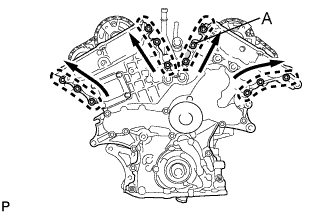
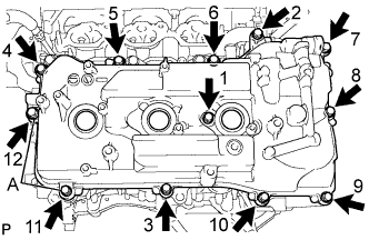
Fully tighten the 12 bolts.
- Torque:
- Bolt A
- 43 N*m { 438 kgf*cm, 32 ft.*lbf }
- Torque:
- Except bolt A
- 21 N*m { 214 kgf*cm, 15 ft.*lbf }
Tech Tips
Tighten the bolts in the order of lower to upper as shown in the illustration.
-
-
INSTALL OIL PAN SUB-ASSEMBLY
-
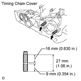
Using an E8 "TORX" socket wrench, install the 2 stud bolts.
- Torque:
- 10 N*m { 102 kgf*cm, 7 ft.*lbf }
-
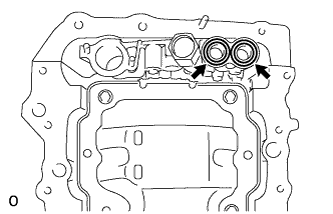
Install 2 new O-rings.
-
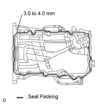
Apply seal packing in a continuous line as shown in the illustration.
Seal packing Toyota Genuine Seal Packing Black, Three Bond 1207B or equivalent Seal diameter 3.0 to 4.0 mm (0.118 to 0.157 in.) Note
-
Remove any oil from the contact surfaces.
-
Install the oil pan within 3 minutes after applying seal packing.
-
Do not start the engine for at least 2 hours after installing.
-
-
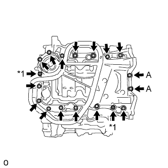
Text in Illustration *1 Nut Install the oil pan with the 16 bolts and 2 nuts.
- Torque:
- Bolts A
- 10 N*m { 102 kgf*cm, 7 ft.*lbf }
- Except bolts A
- 21 N*m { 214 kgf*cm, 15 ft.*lbf }
-
-
INSTALL OIL STRAINER SUB-ASSEMBLY
-
Using an E6 "TORX" socket, install the 2 stud bolts as shown in the illustration.
- Torque:
- 4.0 N*m { 41 kgf*cm, 35 in.*lbf }
-
Text in Illustration *1 Nut Install a new gasket and the oil strainer sub-assembly with the bolt and 2 nuts.
- Torque:
- 10 N*m { 102 kgf*cm, 7 ft.*lbf }
-
-
INSTALL NO. 2 OIL PAN SUB-ASSEMBLY
-
Using an E6 "TORX" socket, install the 2 stud bolts as shown in the illustration.
- Torque:
- 4.0 N*m { 41 kgf*cm, 35 in.*lbf }
-
Apply seal packing in a continuous line as shown in the illustration.
Seal packing Toyota Genuine Seal Packing Black, Three Bond 1207B or equivalent Seal diameter 3.0 to 4.0 mm (0.118 to 0.157 in.) Note
-
Remove any oil from the contact surfaces.
-
Install the No. 2 oil pan sub-assembly within 3 minutes after applying seal packing.
-
Do not start the engine for at least 2 hours after installing.
-
-
Text in Illustration *1 Nut Install the No. 2 oil pan sub-assembly with the 16 bolts and 2 nuts.
- Torque:
- 10 N*m { 102 kgf*cm, 7 ft.*lbf }
-
-
INSTALL CYLINDER HEAD COVER SUB-ASSEMBLY
-
Install 3 new gaskets as shown in the illustration.
-
Install a new cylinder head cover gasket to the cylinder head cover sub-assembly.
-
Apply seal packing as shown in the illustration.
Seal packing Toyota Genuine Seal Packing Black, Three Bond 1207B or equivalent Note
-
Remove any oil from the contact surfaces.
-
Install the head cover within 3 minutes after applying seal packing.
-
Do not start the engine for at least 2 hours after installing.
-
-
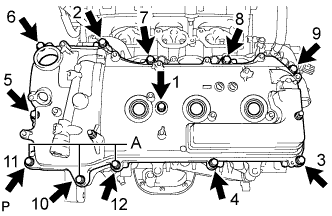
Install the head cover with the 12 bolts and a new seal washer.
- Torque:
- Bolts A
- 21 N*m { 214 kgf*cm, 15 ft.*lbf }
- Except bolts A
- 10 N*m { 102 kgf*cm, 7 ft.*lbf }
Tech Tips
After tightening all bolts, check the tightening torque of 1 and 11. Retighten the bolt if necessary.
-
-
INSTALL CYLINDER HEAD COVER SUB-ASSEMBLY LH
-
Install 3 new gaskets as shown in the illustration.
-
Install a new cylinder head cover gasket to the cylinder head cover sub-assembly LH.
-
Apply seal packing as shown in the illustration.
Seal packing Toyota Genuine Seal Packing Black, Three Bond 1207B or equivalent Note
-
Remove any oil from the contact surfaces.
-
Install the cylinder head cover sub-assembly LH within 3 minutes after applying seal packing.
-
Do not start the engine for at least 2 hours after installing.
-
-
Install the cylinder head cover sub-assembly LH with the 12 bolts and a new seal washer.
- Torque:
- Bolts A
- 21 N*m { 214 kgf*cm, 15 ft.*lbf }
- Except bolts A
- 10 N*m { 102 kgf*cm, 7 ft.*lbf }
Tech Tips
After tightening all bolts, check the tightening torque of 1 and 10. Retighten the bolt if necessary.
-
-
INSTALL WATER INLET HOUSING
-
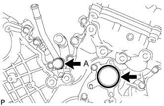
Install 2 new O-rings.
Tech Tips
Apply a small amount of water or soapy water to O-ring (A) shown in the illustration before installation.
-
Install the 2 stud bolts.
- Torque:
- 4.0 N*m { 41 kgf*cm, 35 in.*lbf }
-
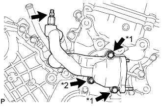
Text in Illustration *1 Bolt *2 Nut Install the inlet water housing with the 2 bolts and nut.
- Torque:
- 10 N*m { 102 kgf*cm, 7 ft.*lbf }
Note
Be careful that the O-ring does not get caught between the parts.
-
Connect the No. 1 water by-pass hose.
-
Apply adhesive around the drain cock.
Adhesive Toyota Genuine Adhesive 1324, Three Bond 1324 or equivalent -
Install the drain cock assembly to the inlet water housing.
- Torque:
- 30 N*m { 306 kgf*cm, 22 ft.*lbf }
-
Install the drain cock plug to the drain cock assembly.
- Torque:
- 13 N*m { 130 kgf*cm, 9 ft.*lbf }
-
Install a new gasket to the thermostat.
-
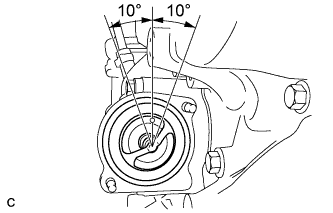
Align the thermostat jiggle valve with the upper stud bolt, and insert the thermostat in the inlet water housing.
Tech Tips
The jiggle valve may be set within 10° of either side of the prescribed position.
-
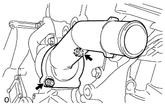
Install the inlet water with the 2 nuts.
- Torque:
- 10 N*m { 102 kgf*cm, 7 ft.*lbf }
-
-
INSTALL CRANKSHAFT PULLEY
-
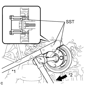
Text in Illustration *1 Hold *2 Turn Using SST, install the pulley bolt.
- SST
- 09213-70011 ( 09213-70020 )
- 09330-00021
- Torque:
- 250 N*m { 2550 kgf*cm, 184 ft.*lbf }
-
-
INSTALL NO. 1 OIL PIPE
-
Make sure that there is no foreign matter on the mesh of the oil control valve filter LH.
Note
Do not touch the mesh when installing the oil control valve filter.
-
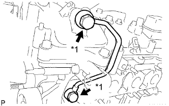
Text in Illustration *1 Oil Pipe Union Install the oil control valve filter LH to the oil pipe union. Install new gaskets and temporarily install the oil pipe (on the head cover side) with the union.
-
Install a new gasket and temporarily install the oil pipe (on the cylinder head side) with the union.
-
Tighten the oil pipe union (on the head cover side).
- Torque:
- 65 N*m { 663 kgf*cm, 48 ft.*lbf }
-
Tighten the oil pipe union (on the cylinder head side).
- Torque:
- 65 N*m { 663 kgf*cm, 48 ft.*lbf }
Note
If the link that connects the gaskets is broken, remove the connecting link by using side cutters or a similar tool.
-
-
INSTALL OIL PIPE
-
Make sure that there is no foreign matter on the mesh of the oil control valve filter RH.
Note
Do not touch the mesh when installing the oil control valve filter.
-
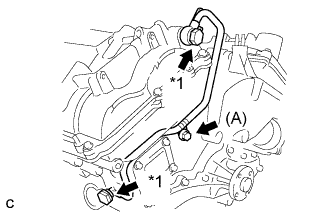
Text in Illustration *1 Oil Pipe Union Install the oil control valve filter RH to the oil pipe union. Install new gaskets and temporarily install the oil pipe (on the head cover side) with the union.
-
Install a new gasket and temporarily install the oil pipe (on the cylinder head side) with the union.
-
Install the bolt (A) to the cylinder head.
- Torque:
- 10 N*m { 102 kgf*cm, 7 ft.*lbf }
-
Tighten the oil pipe union (on the head cover side).
- Torque:
- 65 N*m { 663 kgf*cm, 48 ft.*lbf }
-
Tighten the oil pipe union (on the cylinder head side).
- Torque:
- 65 N*m { 663 kgf*cm, 48 ft.*lbf }
Note
If the link that connects the gaskets is broken, remove the connecting link by using side cutters or a similar tool.
-
-
INSTALL ENGINE HANGERS
-
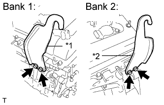
Text in Illustration *1 No. 1 Engine Hanger *2 No. 2 Engine Hanger Install the 2 engine hangers with the 4 bolts as shown in the illustration.
- Torque:
- 33 N*m { 337 kgf*cm, 24 ft.*lbf }
Part No. Item Part No. No. 1 Engine Hanger 12281-31120 No. 2 Engine Hanger 12282-31100 Bolt 91671-10825 -
Attach the engine sling device and hang the engine with the chain block.
-
-
REMOVE ENGINE STAND
-
INSTALL HYBRID VEHICLE TRANSAXLE ASSEMBLY
Tech Tips