EXHAUST PIPE INSTALLATION

Note
When removing or installing the center exhaust pipe assembly, do not subject the temperature switch to impacts.
-
INSTALL NO. 2 OXYGEN SENSOR (for Bank 2 Sensor 2)
-
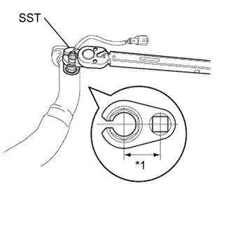
Text in Illustration *1 Fulcrum Length
30 mm
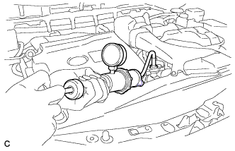
Using SST, install the No. 2 oxygen sensor to the front exhaust pipe assembly.
- SST
- 09224-00010
- Torque:
- without SST
- 44 N*m { 449 kgf*cm, 32 ft.*lbf }
- with SST
- 40 N*m { 408 kgf*cm, 30 ft.*lbf }
Note
-
The "with SST" torque value is effective when using SST with a fulcrum length of 30 mm (1.18 in.).
-
The "with SST" torque value is effective when using a torque wrench with a fulcrum length of 300 mm (11.81 in.) Click here.
-
The "with SST" torque value is effective when SST is parallel to the torque wrench.
-
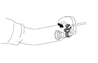
Install the wire harness clamp bracket.
-
-
INSTALL FRONT EXHAUST PIPE ASSEMBLY
-
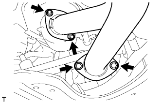
Install a new gasket to the front exhaust pipe assembly.
-
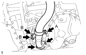
Install the front exhaust pipe assembly with the 2 nuts and 2 bolts (B).
- Torque:
- Bolt B
- 21 N*m { 214 kgf*cm, 15 ft.*lbf }
- Nut
- 55 N*m { 561 kgf*cm, 40 ft.*lbf }
-
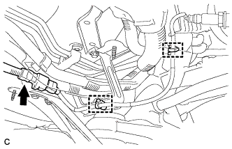
Tighten the bolt (A).
- Torque:
- Bolt A
- 21 N*m { 214 kgf*cm, 15 ft.*lbf }
-
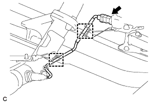
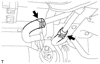
Connect the 2 clamps and No. 2 oxygen sensor connector (for Bank 2 Sensor 2).
-
-
INSTALL FRONT NO. 3 EXHAUST PIPE SUB-ASSEMBLY
-
Install 2 new gaskets to the front No. 3 exhaust pipe sub-assembly.
-
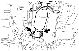
Install the front No. 3 exhaust pipe sub-assembly with the 2 bolts and 2 nuts.
- Torque:
- Bolt
- 55 N*m { 561 kgf*cm, 40 ft.*lbf }
- Nut
- 55 N*m { 561 kgf*cm, 40 ft.*lbf }
-
-
INSTALL OXYGEN SENSOR (for Bank 1 Sensor 2)
-
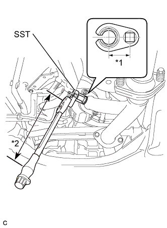
Text in Illustration *1 Fulcrum Length
30 mm
*2 Fulcrum Length
300 mm
Using SST, install the oxygen sensor to the center exhaust pipe assembly.
- SST
- 09224-00010
- Torque:
- without SST
- 44 N*m { 449 kgf*cm, 32 ft.*lbf }
- with SST
- 40 N*m { 408 kgf*cm, 30 ft.*lbf }
Note
-
The "with SST" torque value is effective when using SST with a fulcrum length of 30 mm (1.18 in.).
-
The "with SST" torque value is effective when using a torque wrench with a fulcrum length of 300 mm (11.81 in.) Click here.
-
The "with SST" torque value is effective when SST is parallel to the torque wrench.
-
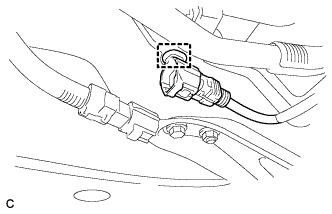
Connect the wire harness clamp.
-
Connect the 2 wire harness clamps and oxygen sensor connector (for Bank 1 Sensor 2).
-
-
INSTALL CENTER EXHAUST PIPE ASSEMBLY (w/ Exhaust Heat Recirculation System)
Note
When removing or installing the center exhaust pipe assembly, do not subject the temperature switch to impacts.
-
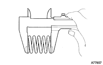
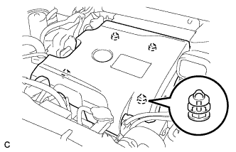
Using a vernier caliper, measure the free length of the compression springs.
Minimum length 41.5 mm (1.64 in.) If the free length is less than the minimum, replace the compression spring.
-
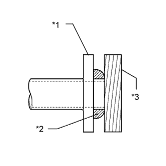
Fully insert a new gasket to the front No. 3 exhaust pipe sub-assembly.
-
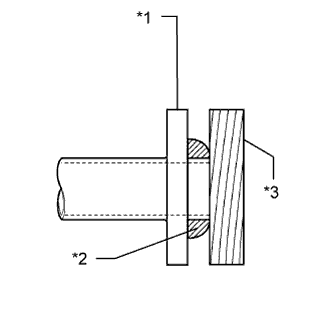
Text in Illustration *1 Front No. 3 Exhaust Pipe Sub-assembly *2 Gasket *3 Wooden Block Using a plastic hammer and wooden block, tap in the new gasket until its surface is flush with the front No. 3 exhaust pipe sub-assembly.
Note
-
Be sure to install the gasket in the correct direction.
-
Do not reuse the gasket.
-
Do not damage the gasket.
-
Do not push in the gasket by using the exhaust pipe when connecting it.
-
-
Connect the center exhaust pipe assembly to the 4 exhaust pipe supports.
-
Install the center exhaust pipe assembly with the 2 bolts and 2 compression springs.
- Torque:
- 43 N*m { 440 kgf*cm, 32 ft.*lbf }
-
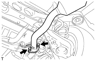
Connect the 2 heater water hoses.
-
-
INSTALL CENTER EXHAUST PIPE ASSEMBLY (w/o Exhaust Heat Recirculation System)
-
Using a vernier caliper, measure the free length of the compression springs.
Minimum length 41.5 mm (1.64 in.) If the free length is less than the minimum, replace the compression spring.
-
Fully insert a new gasket to the front No. 3 exhaust pipe sub-assembly.
-
Text in Illustration *1 Front No. 3 Exhaust Pipe Sub-assembly *2 Gasket *3 Wooden Block Using a plastic hammer and wooden block, tap in the new gasket until its surface is flush with the front No. 3 exhaust pipe sub-assembly.
Note
-
Be sure to install the gasket in the correct direction.
-
Do not reuse the gasket.
-
Do not damage the gasket.
-
Do not push in the gasket by using the exhaust pipe when connecting it.
-
-
Connect the center exhaust pipe assembly to the 4 exhaust pipe supports.
-
Install the center exhaust pipe assembly with the 2 bolts and 2 compression springs.
- Torque:
- 43 N*m { 440 kgf*cm, 32 ft.*lbf }
-
-
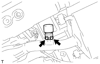
INSTALL HEATER COVER (w/ Exhaust Heat Recirculation System)
-
Install the heater cover with the 2 bolts.
- Torque:
- 9.8 N*m { 100 kgf*cm, 87 in.*lbf }
-
Connect the clamp.
-
-
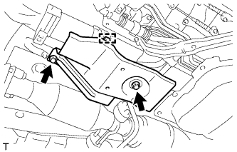
INSTALL EXHAUST PIPE DAMPER
-
Install the exhaust pipe damper with the 2 bolts.
- Torque:
- 19 N*m { 194 kgf*cm, 14 ft.*lbf }
-
-
INSTALL TAIL EXHAUST PIPE ASSEMBLY
-
Using a vernier caliper, measure the free length of the compression springs.
Minimum length 41.5 mm (1.64 in.) If the free length is less than the minimum, replace the compression spring.
-
Fully insert a new gasket to the center exhaust pipe assembly.
-
Text in Illustration *1 Center Exhaust Pipe Assembly *2 Gasket *3 Wooden Block Using a plastic hammer and wooden block, tap in the new gasket until its surface is flush with the center exhaust pipe assembly.
Note
-
Be sure to install the gasket in the correct direction.
-
Do not reuse the gasket.
-
Do not damage the gasket.
-
Do not push in the gasket by using the exhaust pipe when connecting it.
-
-
Connect the tail exhaust pipe assembly to the 2 exhaust pipe supports.
-
Install the tail exhaust pipe assembly with the 2 bolts and 2 compression springs.
- Torque:
- 43 N*m { 440 kgf*cm, 32 ft.*lbf }
-
-
ADD ENGINE COOLANT (for Engine with Exhaust Heat Recirculation System)
-
Tighten the radiator drain cock plug by hand.
-
Tighten the 2 cylinder block drain cock plugs.
- Torque:
- 13 N*m { 130 kgf*cm, 9 ft.*lbf }
-
Loosen the air drain cock plug on the water inlet housing.
-
Add TOYOTA Super Long Life Coolant (SLLC) to the radiator inlet opening until coolant overflows from the air drain cock hole. Then tighten the air drain cock plug to the water inlet housing.
- Torque:
- 13 N*m { 130 kgf*cm, 9 ft.*lbf }
-
Slowly fill the radiator with TOYOTA Super Long Life Coolant (SLLC).
Standard Capacity Item Capacity Engine coolant 11.7 liters (12.4 US qts, 10.2 lmp. qts) Tech Tips
-
TOYOTA vehicles are filled with TOYOTA SLLC at the factory. In order to avoid damage to the engine cooling system and other technical problems, only use TOYOTA SLLC or similar high quality ethylene glycol based non-silicate, non-amine, non-nitrite, non-borate coolant with long-life hybrid organic acid technology (coolant with long-life hybrid organic acid technology is a combination of low phosphates and organic acids).
-
Contact your TOYOTA dealer for further details.
Note
Never use water as a substitute for engine coolant.
-
-
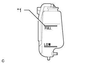
Text in Illustration *1 Full Line Slowly pour coolant into the radiator reservoir tank until it reaches the full line.
-
Install the radiator cap.
-
Squeeze the No. 1 and No. 2 radiator hoses several times by hand, and then check the level of the coolant.
If the coolant level is low, add coolant.
-
Bleed air from the cooling system.
-
Put the engine in inspection mode Click here.
-
Warm up the engine until the thermostat opens. While the thermostat is open, circulate the coolant for several minutes.
Tech Tips
The thermostat open timing can be confirmed by squeezing the No. 2 radiator hose by hand, and checking when the engine coolant starts to flow inside the hose.
-
Maintain the engine speed at 2500 rpm.
-
Squeeze the inlet and No. 1 and No. 2 radiator hoses several times by hand to bleed air.
CAUTION:
When squeezing the radiator hoses:
-
Wear protective gloves.
-
Be careful as the radiator hoses are hot.
-
Keep your hands away from the cooling fans.
Note
-
Make sure that the radiator reservoir still has some coolant in it.
-
If the coolant temperature gauge indicates an excessive temperature, turn off the engine and let it cool.
-
If there is not enough coolant, the engine may overheat or be seriously damaged.
-
If the radiator reservoir does not have enough coolant, perform the following: 1) stop the engine, 2) wait until the coolant has cooled down, and 3) add coolant until the reservoir is filled to the Full line.
-
-
-
Stop the engine and wait until the engine coolant cools down.
-
Add engine coolant to the full line on the radiator reservoir.
-
-
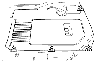
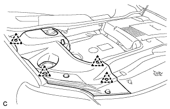
INSTALL FRONT FLOOR COVER LH (w/ Exhaust Heat Recirculation System)
-

Text in Illustration *1 Bolt *2 Screw Connect the 2 clips (B).
-
Install the front floor cover LH with the 2 screws and 4 bolts.
-
Install the clip (A).
-
-
INSPECT FOR COOLANT LEAK (for Engine with Exhaust Heat Recirculation System)
CAUTION:
Do not remove the radiator cap while the engine and radiator are still hot. Pressurized hot engine coolant and steam may be released and cause serious burns.
Note
Before performing each inspection, turn the A/C switch off.
-
Remove the radiator cap.
-
Fill the radiator with coolant and attach a radiator cap tester.
-
Put the engine in inspection mode Click here.
-
Warm up the engine.
-
Using the radiator cap tester, increase the pressure inside the radiator to 118 kPa (1.2 kgf/cm2, 17 psi), and check that the pressure does not drop.
If the pressure drops, check the hoses, radiator, exhaust center pipe assembly and the heater hose around the water temperature switch and engine water pump for leaks. If no external leaks are found, check the heater core, cylinder block and cylinder head.
-
Remove the radiator cap tester.
-
Install the radiator cap.
-
-
INSTALL NO. 1 ENGINE UNDER COVER (w/ Exhaust Heat Recirculation System)
-
INSTALL V-BANK COVER SUB-ASSEMBLY (w/ Exhaust Heat Recirculation System)
-
Fit the 4 retainers and install the V-bank cover sub-assembly.
-
-
INSTALL COOL AIR INTAKE DUCT SEAL (w/ Exhaust Heat Recirculation System)
-
Install the cool air intake duct seal with the 6 clips.
-
-
INSTALL ENGINE ROOM SIDE COVER LH (w/ Exhaust Heat Recirculation System)
-
Install the engine room side cover with the 4 clips.
-
-
INSTALL ENGINE ROOM SIDE COVER (w/ Exhaust Heat Recirculation System)
-
Install the engine room side cover with the 4 clips.
-
-
INSPECT FOR EXHAUST GAS LEAK