EXHAUST HEAT RECIRCULATION SYSTEM Exhaust Heat Recirculation System Circuit
DESCRIPTION
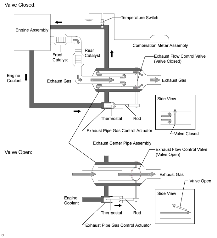
In the exhaust heat recirculation system, coolant is warmed up using conventionally wasted exhaust gas heat to accelerate engine warm-up time, enhancing fuel efficiency and heater performance. Since this system allows the engine to be warmed up with greater efficiency, contributing to low fuel consumption.
The heat recirculator is positioned in the exhaust center pipe assembly after the catalyst. Coolant from the engine flows around the heat recirculator and then returns to the engine. If the engine is started while the engine is cold, the exhaust pipe gas control actuator rod is contracted and the exhaust flow control valve is closed, routing the exhaust gas around the heat recirculator to warm up the coolant.
After the engine coolant temperature rises and the engine has warmed up, the heat of the coolant expands the thermostat and the exhaust pipe gas control actuator rod extends. This opens the exhaust flow control valve to switch to the normal exhaust gas path.
The exhaust flow control valve can also be opened by exhaust gas pressure to prevent insufficient acceleration performance when the engine is cold. In addition, to monitor the engine coolant temperature, a water temperature switch is provided between the engine and the heat recirculator. When the engine coolant temperature is normal, the water temperature switch is closed (on). If the engine coolant temperature is excessively high (overheating), the switch opens (off) and the needle of the water temperature receiver gauge in the combination meter assembly indicates above HI to inform the driver of the malfunction.
WIRING DIAGRAM
Refer to System Diagram Click here.
INSPECTION PROCEDURE
PROCEDURE
-
CHECK HARNESS AND CONNECTOR (TEMPERATURE SWITCH - COMBINATION METER ASSEMBLY)
-
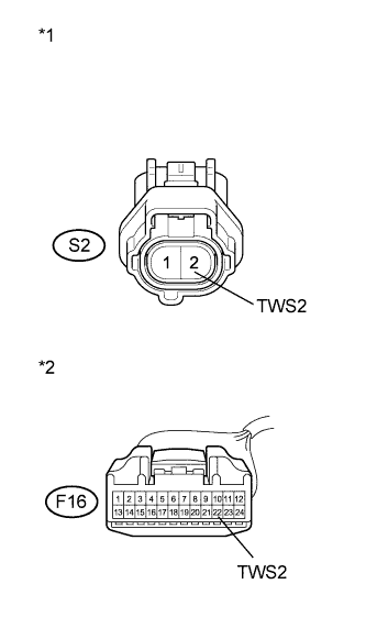
Text in Illustration *1 Front view of wire harness connector
(to Temperature Switch)
*2 Front view of wire harness connector
(to Combination Meter Assembly)
Disconnect the temperature switch connector.
-
Disconnect the combination meter assembly connector.
-
Measure the resistance according to the value(s) in the table below.
Standard Resistance (Check for Open) Tester Connection Condition Specified Condition S2-2 (TWS2) - F16-22 (TWS2) Always Below 1 Ω Standard Resistance (Check for Short) Tester Condition Condition Specified Condition S2-2 (TWS2) or F16-22 (TWS2) - Body ground Always 10 kΩ or higher -
Reconnect the combination meter assembly connector.
-
Reconnect the temperature switch connector.
NG 
REPAIR OR REPLACE HARNESS OR CONNECTOR (TEMPERATURE SWITCH - COMBINATION METER ASSEMBLY)
OK 
-
-
CHECK COMBINATION METER ASSEMBLY
-
Disconnect the temperature switch connector.
-
Turn the power switch on (IG).
-
Check the water temperature receiver gauge in the combination meter assembly.
Result Result Proceed to Water temperature receiver gauge indicates above HI A Water temperature receiver gauge does not change B -
Reconnect the temperature switch connector.
B
REPLACE COMBINATION METER ASSEMBLY Click here
A 
REPLACE TEMPERATURE SWITCH Click here
-