CYLINDER BLOCK INSPECTION

-
INSPECT CONNECTING ROD THRUST CLEARANCE
-
Install the connecting rod cap Click here.
-
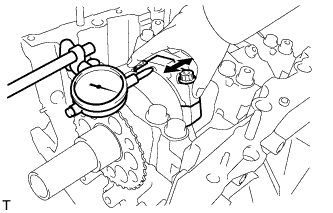
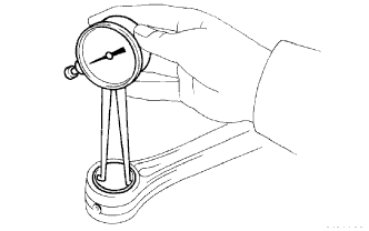
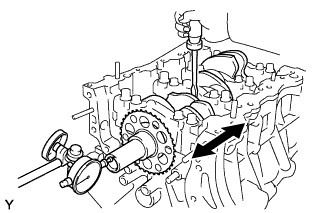
Using a dial indicator, measure the thrust clearance while moving the connecting rod back and forth.
Standard thrust clearance 0.15 to 0.40 mm (0.00591 to 0.0157 in.) Maximum thrust clearance 0.50 mm (0.0197 in.) If the thrust clearance is greater than the maximum, replace the connecting rod assembly. If necessary, replace the crankshaft.
-
-
INSPECT CONNECTING ROD OIL CLEARANCE
-
Clean the crank pin and bearing.
-
Check the crank pin and bearing for pitting and scratches.
-
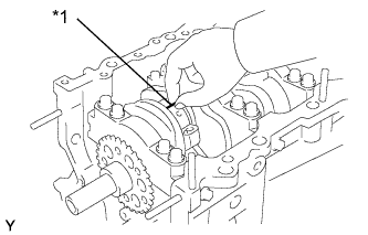
Text in Illustration *1 Plastigage Lay a strip of Plastigage on the crank pin.
-
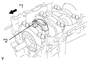
Text in Illustration *1 Engine Front *2 Front Mark Ensure that the front mark of the connecting rod cap is facing forward.
-
Install the connecting rod cap Click here.
Note
Do not turn the crankshaft.
-
Remove the 2 bolts and connecting rod cap Click here.
-
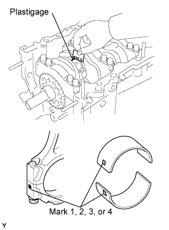
Measure the Plastigage at its widest point.
Standard oil clearance 0.045 to 0.067 mm (0.00177 to 0.00264 in.) Maximum oil clearance 0.070 mm (0.00276 in.) If the oil clearance is greater than the maximum, replace the connecting rod bearings. If necessary, inspect the crankshaft.
Tech Tips
If replacing a bearing, replace it with one that has the same number as its respective connecting rod cap. Each bearing standard thickness is indicated by a number (1, 2, 3 or 4) marked on its surface.
Connecting Rod Diameter Mark Diameter 1 56.000 to 56.006 mm (2.20472 to 2.20496 in.) 2 56.007 to 56.012 mm (2.20500 to 2.20519 in.) 3 56.013 to 56.018 mm (2.20523 to 2.20543 in.) 4 56.019 to 56.024 mm (2.20547 to 2.20566 in.) Connecting Rod Bearing Center Wall Thickness Mark Thickness 1 1.481 to 1.484 mm (0.05831 to 0.05843 in.) 2 1.484 to 1.487 mm (0.05843 to 0.05854 in.) 3 1.487 to 1.490 mm (0.05854 to 0.05866 in.) 4 1.490 to 1.493 mm (0.05866 to 0.05878 in.) Standard crankshaft pin diameter 52.992 to 53.000 mm (2.0863 to 2.0866 in.) Note
Completely remove the Plastigage after the measurement.
-
-
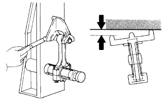
INSPECT CYLINDER BLOCK FOR WARPAGE
-
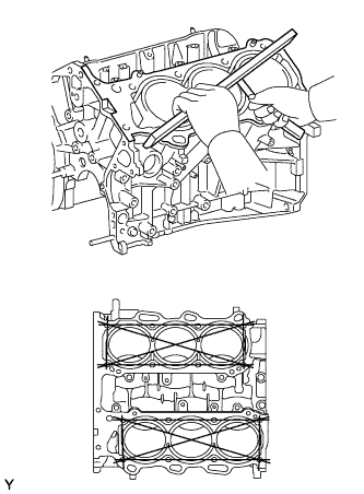
Using a precision straightedge and feeler gauge, measure the warpage of the contact surface of the cylinder head gasket.
Maximum warpage 0.07 mm (0.00276 in.) If the warpage is greater than the maximum, replace the cylinder block sub-assembly.
-
-
INSPECT CYLINDER BORE
-
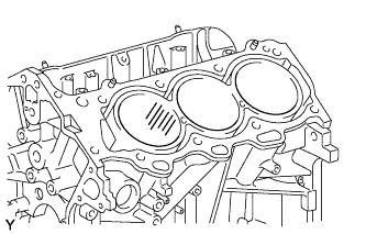
Visually check the cylinder for vertical scratches.
If deep scratches are present, rebore all the 6 cylinders. If necessary, replace the cylinder block.
-
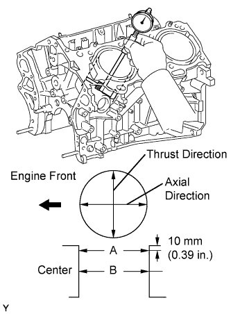
Using a cylinder gauge, measure the cylinder bore diameter at positions A and B in the thrust and axial directions.
Standard diameter 94.000 to 94.012 mm (3.7008 to 3.7013 in.) Maximum diameter 94.130 mm (3.7059 in.) If the average diameter of 4 positions is greater than the maximum, replace the cylinder block sub-assembly.
-
-
INSPECT PISTON
-
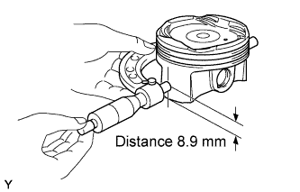
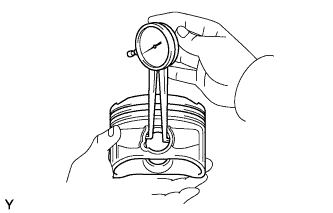
Using a micrometer, measure the piston diameter at right angles to the piston center line where the distance from the piston end is as specified.
Distance 8.9 mm (0.3504 in.) Standard diameter 93.960 to 93.980 mm (3.6992 to 3.7000 in.) Minimum diameter 93.830 mm (3.6941 in.) If the piston diameter is less than the minimum, replace the piston and piston pin as a set.
-
-
INSPECT PISTON OIL CLEARANCE
-
Measure the cylinder bore diameter in the thrust directions.
-
Subtract the piston diameter measurement from the cylinder bore diameter measurement.
Standard oil clearance 0.020 to 0.052 mm (0.000787 to 0.00205 in.) Maximum oil clearance 0.060 mm (0.00236 in.) If the oil clearance is greater than the maximum, replace all the pistons. If necessary, replace the cylinder block sub-assembly.
-
-
INSPECT RING GROOVE CLEARANCE
-
Using a feeler gauge, measure the clearance between a new piston ring and the wall of the ring groove.
Ring Groove Clearance Item Clearance No. 1 0.020 to 0.070 mm (0.000787 to 0.00276 in.) No. 2 0.020 to 0.060 mm (0.000787 to 0.00236 in.) Oil 0.020 to 0.065 mm (0.000787 to 0.00256 in.) If the clearance is not as specified, replace the piston.
-
-
INSPECT PISTON PIN OIL CLEARANCE
-
Using a caliper gauge, measure the inside diameter of the piston pin hole.
Piston Pin Hole Inside Diameter Mark Diameter A 22.001 to 22.004 mm (0.8662 to 0.8663 in.) B 22.004 to 22.007 mm (0.8663 to 0.8664 in.) C 22.007 to 22.010 mm (0.8664 to 0.8665 in.) -
Using a micrometer, measure the piston pin diameter.
Piston Pin Diameter Mark Diameter A 21.997 to 22.000 mm (0.8660 to 0.8661 in.) B 22.000 to 22.003 mm (0.8661 to 0.8663 in.) C 22.003 to 22.006 mm (0.8663 to 0.8664 in.) -
Subtract the piston pin diameter measurement from the piston pin hole diameter measurement.
Standard oil clearance 0.001 to 0.007 mm (0.0000394 to 0.000276 in.) Maximum oil clearance 0.015 mm (0.000591 in.) If the oil clearance is greater than the maximum, replace the piston and piston pin as a set.
-
Using a caliper gauge, measure the inside diameter of the connecting rod bushing.
Bushing Inside Diameter Mark Diameter A 22.005 to 22.008 mm (0.86634 to 0.86645 in.) B 22.009 to 22.011 mm (0.86649 to 0.86657 in.) C 22.012 to 22.014 mm (0.86661 to 0.86669 in.) -
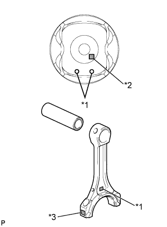
Text in Illustration *1 Front Mark *2 Piston Pin Hole Inside Diameter Mark *3 Connecting Rod Bushing Inside Diameter Mark Subtract the piston pin diameter measurement from the bushing inside diameter measurement.
Standard oil clearance 0.005 to 0.011 mm (0.000197 to 0.000433 in.) Maximum oil clearance 0.030 mm (0.00118 in.) If the oil clearance is greater than the maximum, replace the bushing. If necessary, replace the connecting rod and piston pin as a set.
-
-
INSPECT PISTON RING END GAP
-
Insert the piston ring into the cylinder bore.
-
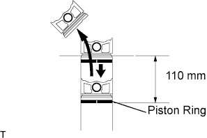
Using a piston, push the piston ring slightly beyond the bottom of the ring travel, 110 mm (4.33 in.) from the top of the cylinder block sub-assembly.
-

Using a feeler gauge, measure the end gap.
Standard End Gap Item End Gap No. 1 0.22 to 0.32 mm (0.00866 to 0.0126 in.) No. 2 0.35 to 0.45 mm (0.0138 to 0.0177 in.) Oil 0.10 to 0.40 mm (0.00394 to 0.0157 in.) Maximum End Gap Item End Gap No. 1 0.50 mm (0.0197 in.) No. 2 0.85 mm (0.0335 in.) Oil 0.60 mm (0.0236 in.) If the end gap is greater than the maximum, replace the piston ring. If the end gap is greater than the maximum even with a new piston ring, rebore all the 6 cylinders or replace the cylinder block sub-assembly.
-
-
INSPECT CRANKSHAFT THRUST CLEARANCE
-
Install the crankshaft bearing cap Click here.
-
Using a dial indicator, measure the thrust clearance while prying the crankshaft back and forth with a screwdriver.
Standard thrust clearance 0.04 to 0.24 mm (0.00157 to 0.00945 in.) Maximum thrust clearance 0.30 mm (0.0118 in.) If the thrust clearance is greater than the maximum, replace the thrust washers as a set. If necessary, replace the crankshaft.
Thrust washer thickness 2.43 to 2.48 mm (0.0957 to 0.0976 in.)
-
-
INSPECT CONNECTING ROD SUB-ASSEMBLY
-
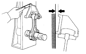
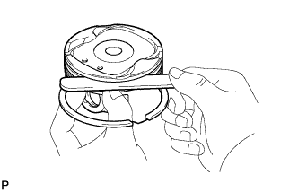
Using a rod aligner and feeler gauge, check the connecting rod alignment.
-
Check for out-of-alignment.
Maximum out-of-alignment 0.05 mm (0.00197 in.) per 100 mm (3.94 in.) If the out-of-alignment is greater than the maximum, replace the connecting rod sub-assembly.
-
Check for twist.
Maximum twist 0.15 mm (0.00591 in.) per 100 mm (3.94 in.) If the twist is greater than the maximum, replace the connecting rod sub-assembly.
-
-
-
INSPECT CONNECTING ROD BOLT
-
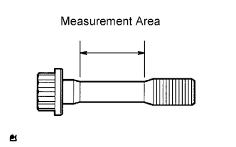
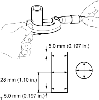
Using a vernier caliper, measure the diameter of the bolt in the area shown in the illustration.
Standard diameter 7.2 to 7.3 mm (0.283 to 0.287 in.) Minimum diameter 7.0 mm (0.276 in.) Tech Tips
-
Diameter measurements should be done at several points.
-
If the diameter is less than the minimum, replace the connecting rod bolt with a new one. Failure to do so may lead to engine damage.
-
If there is any thread deformation, replace the connecting rod bolt with a new one.
-
-
-
INSPECT CRANKSHAFT
-
Inspect for runout.
-
Clean the crank journal.
-
Place the crankshaft on V-blocks.
-
Using a dial indicator, measure the runout at the center journal.
Maximum runout 0.06 mm (0.00236 in.) If the runout is greater than the maximum, replace the crankshaft.
-
-
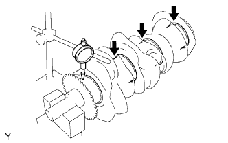
Inspect the main journals.
-
Using a micrometer, measure the diameter of each main journal.
Standard journal diameter 60.988 to 61.000 mm (2.4011 to 2.4016 in.) If the diameter is not as specified, check the oil clearance. If necessary, replace the crankshaft.
-
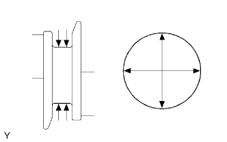
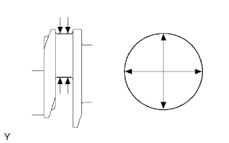
Check each main journal for taper and out-of-round as shown in the illustration.
Maximum taper and out-of-round 0.02 mm (0.000787 in.) If the taper and out-of-round is greater than the maximum, replace the crankshaft.
-
-
Inspect the crank pin.
-
Using a micrometer, measure the diameter of each crank pin.
Crank pin diameter 52.992 to 53.000 mm (2.0863 to 2.0866 in.) If the diameter is not as specified, check the oil clearance. If necessary, replace the crankshaft.
-
Check each crank pin for taper and out-of-round as shown in the illustration.
Maximum taper and out-of-round 0.02 mm (0.000787 in.) If the taper and out-of-round is greater than the maximum, replace the crankshaft.
-
-
-
INSPECT CRANKSHAFT OIL CLEARANCE
-
Check the crank journal and crankshaft bearing for pitting and scratches.
-
Install the crankshaft bearing Click here.
-
Place the crankshaft on the cylinder block.
-
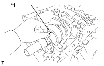
Text in Illustration *1 Plastigage Lay a strip of Plastigage across each journal.
-
Examine the front marks and numbers to install the crankshaft bearing caps on the cylinder block.
Tech Tips
A number is marked on each main bearing cap to indicate the installation position.
-
Install the main bearing cap Click here.
Note
Do not turn the crankshaft.
-
Remove the main bearing caps Click here.
-
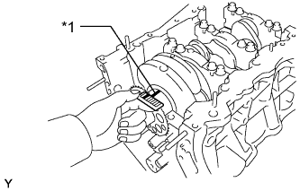
Text in Illustration *1 Plastigage Measure the Plastigage at its widest point.
Standard oil clearance 0.026 to 0.047 mm (0.00102 to 0.00185 in.) Maximum oil clearance 0.050 mm (0.00197 in.) If the oil clearance is greater than the maximum, replace the bearings. If necessary, replace the crankshaft.
Note
Completely remove the Plastigage after the measurement.
-
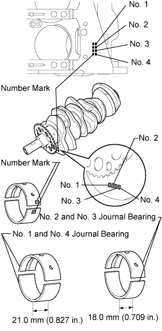
If replacing a bearing, replace it with one having the same number. If the number of the bearing cannot be determined, select the correct bearing by adding together the numbers imprinted on the cylinder block and crankshaft, then refer to the table below for the appropriate bearing number. There are 5 sizes of standard bearings, marked "1", "2", "3", "4" and "5" accordingly.
Journal Bearing Cylinder block + Crankshaft 0 - 5 6 - 11 12 - 17 18 - 23 24 - 28 Bearing to be used "1" "2" "3" "4" "5" Tech Tips
EXAMPLE: Cylinder block "11" + Crankshaft "06" = Total number 17 (Use bearing "3")
Crankshaft Main Journal Diameter Mark Diameter "00" 60.999 to 61.000 mm (2.40153 to 2.40157 in.) "01" 60.998 to 60.999 mm (2.40149 to 2.40153 in.) "02" 60.997 to 60.998 mm (2.40145 to 2.40149 in.) "03" 60.996 to 60.997 mm (2.40141 to 2.40145 in.) "04" 60.995 to 60.996 mm (2.40137 to 2.40141 in.) "05" 60.994 to 60.995 mm (2.40133 to 2.40137 in.) "06" 60.993 to 60.994 mm (2.40129 to 2.40133 in.) "07" 60.992 to 60.993 mm (2.40126 to 2.40129 in.) "08" 60.991 to 60.992 mm (2.40122 to 2.40126 in.) "09" 60.990 to 60.991 mm (2.40118 to 2.40122 in.) "10" 60.989 to 60.990 mm (2.40114 to 2.40118 in.) "11" 60.988 to 60.989 mm (2.40110 to 2.40114 in.) Standard Upper Bearing Center Wall Thickness (No. 1 and No. 4 journal) Mark Thickness "1" 2.500 to 2.503 mm (0.09843 to 0.09854 in.) "2" 2.503 to 2.506 mm (0.09854 to 0.09866 in.) "3" 2.506 to 2.509 mm (0.09866 to 0.09878 in.) "4" 2.509 to 2.512 mm (0.09878 to 0.09890 in.) "5" 2.512 to 2.515 mm (0.09890 to 0.09902 in.) Standard Lower Bearing Center Wall Thickness (No. 1 and No. 4 journal) Mark Thickness "1" 2.478 to 2.481 mm (0.09756 to 0.09768 in.) "2" 2.481 to 2.484 mm (0.09768 to 0.09780 in.) "3" 2.484 to 2.487 mm (0.09780 to 0.09791 in.) "4" 2.487 to 2.490 mm (0.09791 to 0.09803 in.) "5" 2.490 to 2.493 mm (0.09803 to 0.09815 in.) Standard Upper Bearing Center Wall Thickness (No. 2 and No. 3 journal) Mark Thickness "1" 2.478 to 2.481 mm (0.09756 to 0.09768 in.) "2" 2.481 to 2.484 mm (0.09768 to 0.09780 in.) "3" 2.484 to 2.487 mm (0.09780 to 0.09791 in.) "4" 2.487 to 2.490 mm (0.09791 to 0.09803 in.) "5" 2.490 to 2.493 mm (0.09803 to 0.09815 in.) Standard Lower Bearing Center Wall Thickness (No. 2 and No. 3 journal) Mark Thickness "1" 2.500 to 2.503 mm (0.09843 to 0.09854 in.) "2" 2.503 to 2.506 mm (0.09854 to 0.09866 in.) "3" 2.506 to 2.509 mm (0.09866 to 0.09878 in.) "4" 2.509 to 2.512 mm (0.09878 to 0.09890 in.) "5" 2.512 to 2.515 mm (0.09890 to 0.09902 in.)
-
-
INSPECT CRANKSHAFT BEARING CAP SET BOLT
-
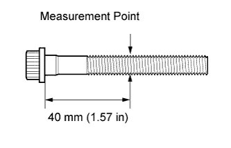
Using a vernier caliper, measure the diameter of the threads at the measurement point shown in the illustration.
Standard diameter 10.8 to 11.0 mm (0.4252 to 0.4331 in.) Minimum diameter 10.7 mm (0.4213 in.) Tech Tips
-
If the diameter is less than the minimum, replace the crankshaft bearing cap set bolt. Failure to do so may lead to engine damage.
-
If there is any thread deformation, replace the crankshaft bearing cap set bolt with a new one.
-
-
-
INSPECT NO. 1 OIL NOZZLE SUB-ASSEMBLY
-
Check the oil nozzles for damage or clogs.
Tech Tips
If there is damage or clogs, replace the oil nozzle.
-