CYLINDER HEAD DISASSEMBLY

Tech Tips
-
Select the No. 1 valve rocker arm sub-assemblies, inner compression springs and valve spring retainers based on the identification mark on the cylinder head.
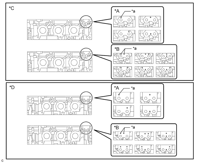
Text in Illustration *A Type A *B Type B *C Cylinder Head RH *D Cylinder Head LH *a Identification Mark - - Type Identification Mark Inner Compression Spring Shape A 1 Hole Straight B 2 Holes Taper -
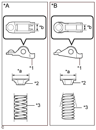
There are 2 types of No. 1 valve rocker arm sub-assemblies, inner compression springs and valve spring retainers. The 2 types are not interchangeable.
Text in Illustration *A Type A *B Type B *1 No. 1 Valve Rocker Arm Sub-assembly *2 Valve Spring Retainer *3 Inner Compression Spring *a Valve Spring Retainer Diameter *b No. 1 Valve Rocker Arm Sub-assembly Roller Width Type No. 1 Valve Rocker Arm Sub-assembly Roller Width Valve Spring Retainer Diameter Inner Compression Spring Shape A 10.7 mm (0.421 in.) 23.4 mm (0.921 in.) Straight B 8.0 mm (0.315 in.) 18.9 mm (0.744 in.) Taper
-
REMOVE VALVE STEM CAP
-
Remove the valve stem caps from the cylinder heads.
Tech Tips
Arrange the removed parts in the correct order.
-
-
REMOVE INTAKE VALVE
Tech Tips
Type A and Type B can be distinguished by the shape of the inner compression spring.
Text in Illustration *A Type A *B Type B *1 No. 1 Valve Rocker Arm Sub-assembly *2 Valve Spring Retainer *3 Inner Compression Spring *a Valve Spring Retainer Diameter *b No. 1 Valve Rocker Arm Sub-assembly Roller Width Type No. 1 Valve Rocker Arm Sub-assembly Roller Width Valve Spring Retainer Diameter Inner Compression Spring Shape A 10.7 mm (0.421 in.) 23.4 mm (0.921 in.) Straight B 8.0 mm (0.315 in.) 18.9 mm (0.744 in.) Taper
-
Type A:
-
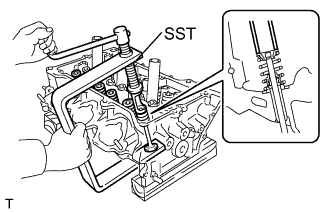
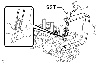
Using SST, compress the inner compression spring and remove the valve spring retainer locks.
- SST
- 09202-70020 ( 09202-00010, 09202-01010, 09202-01020 )
-
-
Type B:
-

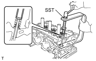
Using SST, compress the inner compression spring and remove the valve spring retainer locks.
- SST
- 09202-70020 ( 09202-01010, 09202-01020 )
- 09202-00020
-
-
Remove the valve spring retainer, inner compression spring and intake valve.
Tech Tips
Arrange the removed parts in the correct order.
-
-
REMOVE EXHAUST VALVE
Tech Tips
Type A and Type B can be distinguished by the shape of the inner compression spring.
Text in Illustration *A Type A *B Type B *1 No. 1 Valve Rocker Arm Sub-assembly *2 Valve Spring Retainer *3 Inner Compression Spring *a Valve Spring Retainer Diameter *b No. 1 Valve Rocker Arm Sub-assembly Roller Width Type No. 1 Valve Rocker Arm Sub-assembly Roller Width Valve Spring Retainer Diameter Inner Compression Spring Shape A 10.7 mm (0.421 in.) 23.4 mm (0.921 in.) Straight B 8.0 mm (0.315 in.) 18.9 mm (0.744 in.) Taper
-
Type A:
-
Using SST, compress the inner compression spring and remove the valve spring retainer locks.
- SST
- 09202-70020 ( 09202-00010, 09202-01010, 09202-01020 )
-
-
Type B:
-
Using SST, compress the inner compression spring and remove the valve spring retainer locks.
- SST
- 09202-70020 ( 09202-01010, 09202-01020 )
- 09202-00020
-
-
Remove the valve spring retainer, inner compression spring and exhaust valve.
Tech Tips
Arrange the removed parts in the correct order.
-
-
REMOVE VALVE STEM OIL SEAL
-
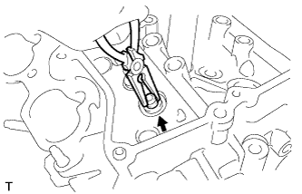
Using needle-nose pliers, remove the valve stem oil seals.
-
-
REMOVE VALVE SPRING SEAT
-
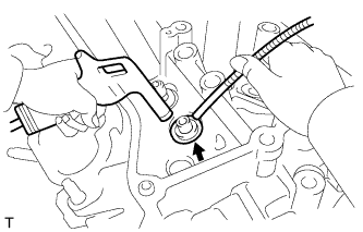
Using compressed air and a Magnet Hand, remove the valve spring seats by blowing air onto them.
-
-
REMOVE NO. 1 STRAIGHT SCREW PLUG
-
Using a 10 mm hexagon wrench, remove the 4 No. 1 straight screw plugs and 4 gaskets.
Note
If water leaks from a straight screw plug or the plug is corroded, replace it.
-
-
REMOVE NO. 2 STRAIGHT SCREW PLUG
-
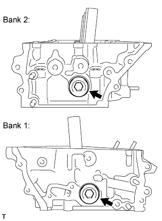
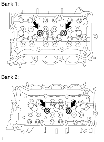
Using a 14 mm hexagon wrench, remove the 2 No. 2 straight screw plugs and 2 gaskets.
Note
If water leaks from a straight screw plug or the plug is corroded, replace it.
-