CYLINDER HEAD INSPECTION

-
INSPECT CYLINDER HEAD SUB-ASSEMBLY
-
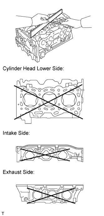
Using a precision straightedge and feeler gauge, measure the warpage of the contact surface of the cylinder block sub-assembly and manifolds.
Standard Warpage Item Warpage Cylinder head lower 0.05 mm (0.00197 in.) Intake 0.08 mm (0.00315 in.) Exhaust 0.08 mm (0.00315 in.) Maximum Warpage Item Warpage Cylinder head lower 0.10 mm (0.00394 in.) Intake 0.10 mm (0.00394 in.) Exhaust 0.10 mm (0.00394 in.) If the warpage is greater than the maximum, replace the cylinder head sub-assembly.
-
-
INSPECT CYLINDER HEAD FOR CRACKS
-
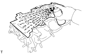
Using a dye penetrate, check the intake ports, exhaust ports and cylinder surface for cracks.
If cracked, replace the cylinder head sub-assembly.
-
-
INSPECT INTAKE VALVE
-
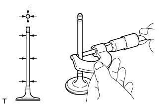
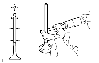
Using a micrometer, measure the diameter of the valve stem.
Standard valve stem diameter 5.470 to 5.485 mm (0.2154 to 0.2159 in.) If the valve stem is not as specified, check the oil clearance.
-
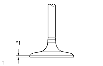
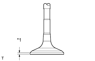
Text in Illustration *1 Margin Thickness Using a vernier caliper, measure the valve head margin thickness.
Standard margin thickness 1.0 mm (0.0394 in.) Minimum margin thickness 0.5 mm (0.0197 in.) If the margin thickness is less than the minimum, replace the intake valve.
-
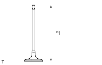
Text in Illustration *1 Overall Length Using a vernier caliper, measure the valve overall length.
Standard overall length 105.85 mm (4.1673 in.) Minimum overall length 105.35 mm (4.1476 in.) If the overall length is less than the minimum, replace the intake valve.
-
-
INSPECT EXHAUST VALVE
-
Using a micrometer, measure the diameter of the valve stem.
Standard valve stem diameter 5.465 to 5.480 mm (0.2152 to 0.2157 in.) If the valve stem is not as specified, check the oil clearance.
-
Text in Illustration *1 Margin Thickness Using a vernier caliper, measure the valve head margin thickness.
Standard margin thickness 1.0 mm (0.0394 in.) Minimum margin thickness 0.5 mm (0.0197 in.) If the margin thickness is less than the minimum, replace the exhaust valve.
-
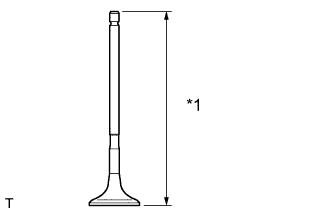
Text in Illustration *1 Overall Length Using a vernier caliper, measure the valve overall length.
Standard overall length 110.40 mm (4.3464 in.) Minimum overall length 109.90 mm (4.3268 in.) If the overall length is less than the minimum, replace the exhaust valve.
-
-
INSPECT INTAKE VALVE SEAT
-
Apply a light coat of Prussian blue to the valve face.
-
Lightly press the valve face against the valve seat.
-
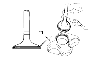
Text in Illustration *1 Width Check the valve face and valve spring seat by using the following procedure:
-
If Prussian blue appears around the entire valve face, the valve face is concentric. If not, replace the valve.
-
If Prussian blue appears around the entire valve seat, the guide and valve face are concentric. If not, resurface the valve spring seat.
-
Check that the valve spring seat contacts in the middle of the valve face with the width between 1.1 and 1.6 mm (0.0433 and 0.0630 in.).
-
-
-
INSPECT EXHAUST VALVE SEAT
-
Apply a light coat of Prussian blue to the valve face.
-
Lightly press the valve face against the valve spring seat.
-
Text in Illustration *1 Width Check the valve face and valve spring seat by using the following procedure:
-
If Prussian blue appears around the entire valve face, the valve face is concentric. If not, replace the valve.
-
If Prussian blue appears around the entire valve seat, the guide and valve face are concentric. If not, resurface the valve spring seat.
-
Check that the valve spring seat contacts in the middle of the valve face with the width between 1.1 and 1.6 mm (0.0433 and 0.0630 in.).
-
-
-
INSPECT INNER COMPRESSION SPRING
Tech Tips
Type A and Type B can be distinguished by the shape of the inner compression spring.
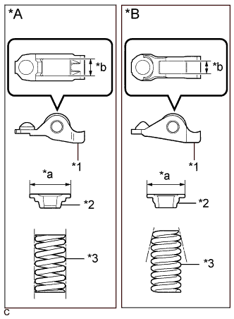
Text in Illustration *A Type A *B Type B *1 No. 1 Valve Rocker Arm Sub-assembly *2 Valve Spring Retainer *3 Inner Compression Spring *a Valve Spring Retainer Diameter *b No. 1 Valve Rocker Arm Sub-assembly Roller Width Type No. 1 Valve Rocker Arm Sub-assembly Roller Width Valve Spring Retainer Diameter Inner Compression Spring Shape A 10.7 mm (0.421 in.) 23.4 mm (0.921 in.) Straight B 8.0 mm (0.315 in.) 18.9 mm (0.744 in.) Taper
-
Type A:
-
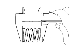
Using vernier calipers, measure the free length of the inner compression spring.
Free length 45.91 mm (1.8075 in.) If the free length is not as specified, replace the inner compression spring.
-
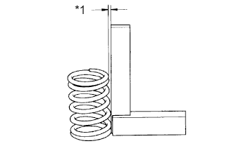
Text in Illustration *1 Deviation Using a steel square, measure the deviation of the inner compression spring.
Maximum deviation 1.0 mm (0.0394 in.) If the deviation is greater than the maximum, replace the inner compression spring.
-
-
Type B:
-
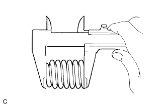
Using vernier calipers, measure the free length of the inner compression spring.
Free length 50.55 mm (1.9902 in.) If the free length is not as specified, replace the inner compression spring.
-
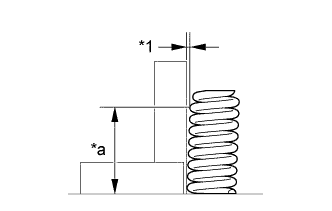
Text in Illustration *1 Deviation *a 40 mm (1.57 in.) Using a steel square, measure the deviation of the inner compression spring.
Maximum deviation 1.4 mm (0.0551 in.) If the deviation is greater than the maximum, replace the inner compression spring.
-
-
-
INSPECT VALVE GUIDE BUSH OIL CLEARANCE
-
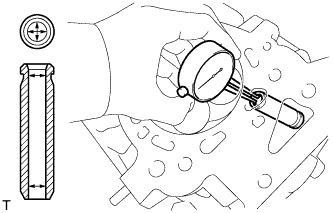
Using a caliper gauge, measure the inside diameter of the valve guide bush.
Standard bush inside diameter 5.510 to 5.530 mm (0.2169 to 0.2177 in.) -
Subtract the valve stem diameter measurement from the valve guide bush inside diameter measurement.
Standard Oil Clearance Item Clearance Intake 0.025 to 0.060 mm (0.000984 to 0.00236 in.) Exhaust 0.030 to 0.065 mm (0.00118 to 0.00256 in.) Maximum Oil Clearance Item Clearance Intake 0.08 mm (0.00315 in.) Exhaust 0.10 mm (0.00394 in.) If the clearance is greater than the maximum, replace the valve and valve guide bush.
-