ENGINE UNIT INSTALLATION

-
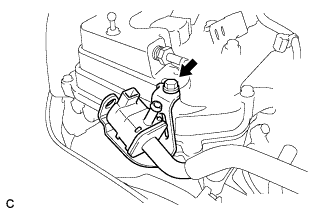
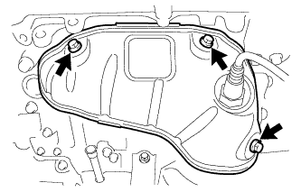
INSTALL ENGINE OIL LEVEL SENSOR
-
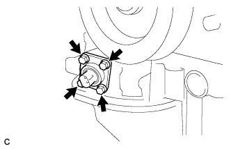
Install the engine oil level sensor with the 4 bolts.
- Torque:
- 8.2 N*m { 84 kgf*cm, 73 in.*lbf }
-
-
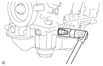
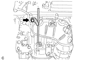
INSTALL ENGINE COOLANT TEMPERATURE SENSOR
-
Install a new gasket onto the engine coolant temperature sensor.
-
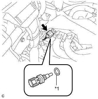
Text in Illustration *1 New Gasket Install the engine coolant temperature sensor and gasket.
- Torque:
- 20 N*m { 204 kgf*cm, 15 ft.*lbf }
-
Connect the engine coolant temperature sensor connector.
-
-
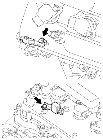
INSTALL KNOCK CONTROL SENSOR
-
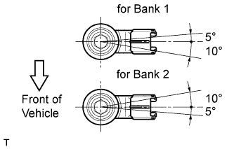
Install the 2 knock control sensors with the 2 bolts as shown in the illustration.
- Torque:
- 20 N*m { 204 kgf*cm, 15 ft.*lbf }
Note
Make sure that each knock control sensor is in the correct position.
-
Connect the 2 knock control sensor connectors.
-
-
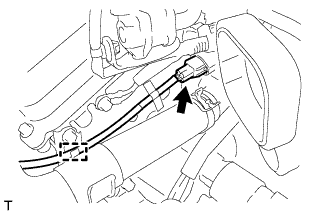
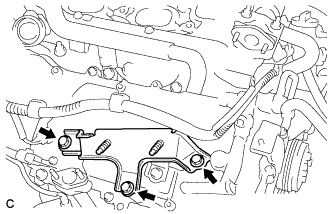
INSTALL SENSOR WIRE
-
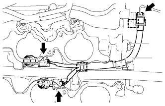
Connect the 2 clamps, 2 knock control sensor connectors and knock control sensor wire connector.
-
-
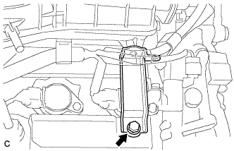
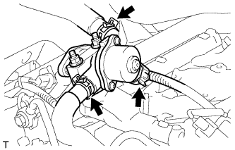
INSTALL ENGINE OIL PRESSURE SWITCH ASSEMBLY
-
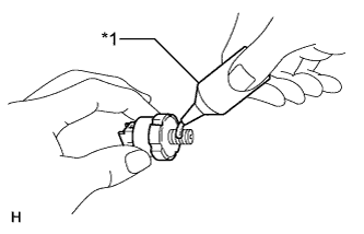
Text in Illustration *1 Adhesive Clean the threads of the oil pressure switch. Apply adhesive to 2 or 3 threads of the oil pressure switch assembly.
Adhesive Toyota Genuine Adhesive 1344, Three Bond 1344 or equivalent -
Using a 24 mm deep socket wrench, install the oil pressure switch.
- Torque:
- 15 N*m { 153 kgf*cm, 11 ft.*lbf }
Note
Do not start the engine within 1 hour after installation to prevent oil leaks.
-
-
INSTALL NO. 1 VACUUM SWITCHING VALVE
-
Install the No. 1 vacuum switching valve with the bolt.
- Torque:
- 10 N*m { 102 kgf*cm, 7 ft.*lbf }
-
-
INSTALL RADIO SETTING CONDENSER
-
Install the 2 radio setting condensers with the 2 bolts.
- Torque:
- 10 N*m { 102 kgf*cm, 7 ft.*lbf }
-
-
INSTALL WATER PUMP PULLEY
-
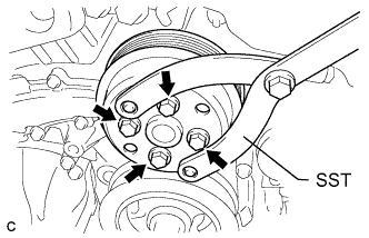
Temporarily install the water pump pulley with the 4 bolts.
-
Using SST, hold the water pump pulley.
- SST
- 09960-10010 ( 09962-01000, 09963-00700 )
-
Tighten the 4 bolts.
- Torque:
- 21 N*m { 214 kgf*cm, 15 ft.*lbf }
-
-
INSTALL NO. 2 TIMING GEAR COVER
-
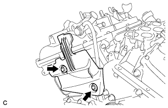
Install the No. 2 timing gear cover with the 2 bolts.
- Torque:
- 6.0 N*m { 61 kgf*cm, 53 in.*lbf }
-
-
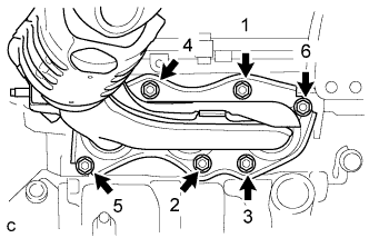
INSTALL V-RIBBED BELT TENSIONER ASSEMBLY
-
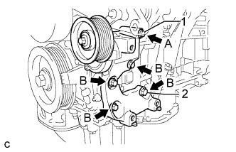
Temporarily install the V-ribbed belt tensioner assembly with the 5 bolts.
Tech Tips
Each bolt length is as follows:
A: 70 mm (2.76 in.)
B: 33 mm (1.30 in.)
-
Install the V-ribbed belt tensioner assembly by tightening the bolt 1 and bolt 2 in the order shown in the illustration.
- Torque:
- 43 N*m { 438 kgf*cm, 32 ft.*lbf }
-
Tighten the other bolts.
- Torque:
- 43 N*m { 438 kgf*cm, 32 ft.*lbf }
-
-
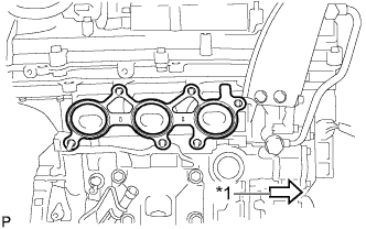
INSTALL EXHAUST MANIFOLD SUB-ASSEMBLY LH
-
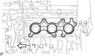
Text in Illustration *1 Front Install a new gasket as shown in the illustration.
-
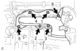
Install the exhaust manifold sub-assembly LH with the 6 nuts in the order shown in the illustration.
- Torque:
- 21 N*m { 214 kgf*cm, 15 ft.*lbf }
-
-
INSTALL NO. 2 EXHAUST MANIFOLD HEAT INSULATOR
-
Install the No. 2 exhaust manifold heat insulator with the 3 bolts.
- Torque:
- 8.5 N*m { 87 kgf*cm, 75 in.*lbf }
-
Connect the sensor wire to the radiator pipe clamp.
-
Connect the air fuel ratio sensor connector (for Bank 2 Sensor 1).
-
-
INSTALL NO. 2 MANIFOLD STAY
-
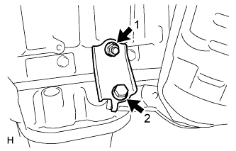
Install the No. 2 manifold stay by tightening the bolt and nut in the order shown in the illustration.
- Torque:
- 34 N*m { 347 kgf*cm, 25 ft.*lbf }
-
-
INSTALL NO. 2 ENGINE OIL LEVEL DIPSTICK GUIDE
-
Install a new O-ring to the No. 2 engine oil level dipstick guide.
-
Apply a light coat of engine oil to the O-ring.
-
Push in the No. 2 engine oil level dipstick guide end into the No. 1 engine oil level dipstick guide.
-
Install the No. 2 engine oil level dipstick guide with the bolt.
- Torque:
- 21 N*m { 214 kgf*cm, 15 ft.*lbf }
-
Install the engine oil level dipstick.
-
-
INSTALL EXHAUST MANIFOLD SUB-ASSEMBLY RH
-
Text in Illustration *1 Front Install a new gasket as shown in the illustration.
-
Install the exhaust manifold sub-assembly RH with the 6 nuts in the order shown in the illustration.
- Torque:
- 21 N*m { 214 kgf*cm, 15 ft.*lbf }
-
-
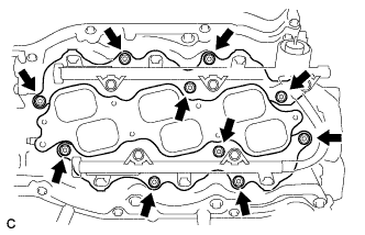
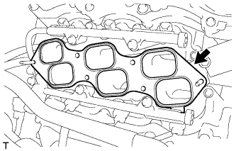
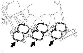
INSTALL INTAKE MANIFOLD
Note
DO NOT apply oil to the bolts listed below:
Tightening Part Intake Manifold and Cylinder Head Sub-assembly RH Intake Manifold and Cylinder Head Sub-assembly LH
-
Set a new gasket on each cylinder head.
Note
-
Align the port holes of the gasket and cylinder head.
-
Make sure that the gasket is installed in the correct direction.
-
-
Set the intake manifold on the cylinder heads.
-
Install and tighten the 6 bolts and 4 nuts uniformly in several steps.
- Torque:
- 21 N*m { 214 kgf*cm, 15 ft.*lbf }
-
-
INSTALL NO. 2 ENGINE MOUNTING STAY RH
-
Install the No. 2 engine mounting stay RH with the bolt.
- Torque:
- 21 N*m { 214 kgf*cm, 15 ft.*lbf }
-
-
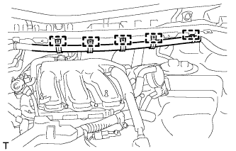
INSTALL IGNITION COIL ASSEMBLY
-
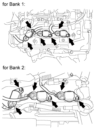
Install the 6 ignition coils with the 6 bolts.
- Torque:
- 10 N*m { 102 kgf*cm, 7 ft.*lbf }
-
Connect the 6 ignition coil connectors.
-
-
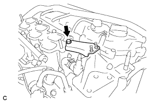
INSTALL NO. 1 SURGE TANK STAY
-
Install the No. 1 surge tank stay with the bolt.
- Torque:
- 21 N*m { 214 kgf*cm, 15 ft.*lbf }
-
-
INSTALL EGR DELIVERY CHAMBER
-
Set a new No. 2 intake manifold gasket.
-
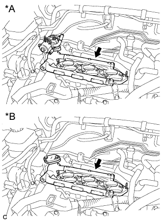
Text in Illustration *A w/ EGR System *B w/o EGR System Install the EGR delivery chamber.
-
Connect the 2 water hoses and connector (w/ EGR System).
-
-
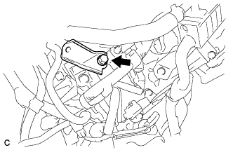
INSTALL NO. 1 EGR COOLER BRACKET (w/ EGR System)
-
Install the No. 1 EGR cooler bracket with the 3 bolts.
- Torque:
- 21 N*m { 214 kgf*cm, 15 ft.*lbf }
-
-
INSTALL EGR COOLER ASSEMBLY (w/ EGR System)
-
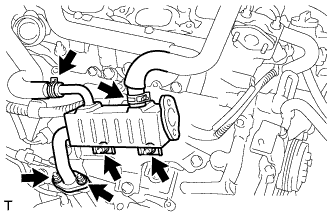
Install a new gasket and the EGR cooler assembly with the 4 nuts.
- Torque:
- 21 N*m { 214 kgf*cm, 15 ft.*lbf }
-
Connect the 2 water hoses.
-
-
INSTALL NO. 1 EGR PIPE (w/ EGR System)
-
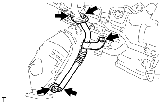
Install 2 new gaskets and No. 1 EGR pipe with the bolt and 4 nuts.
- Torque:
- 21 N*m { 214 kgf*cm, 15 ft.*lbf }
-
-
INSTALL NO. 2 EGR PIPE (w/ EGR System)
-
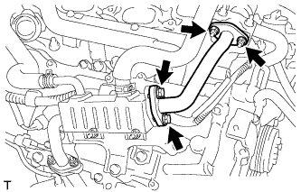
Install 2 new gaskets and the No. 2 EGR pipe with the 2 nuts and 2 bolts.
- Torque:
- 21 N*m { 214 kgf*cm, 15 ft.*lbf }
-
-
INSTALL THROTTLE BODY BRACKET
-
Install the throttle body bracket with the bolt.
- Torque:
- 21 N*m { 214 kgf*cm, 15 ft.*lbf }
-
-
INSTALL INTAKE AIR SURGE TANK ASSEMBLY
NOTICE DO NOT apply oil to the bolts listed below: Tightening Part Surge Tank and Intake Manifold No. 1 Surge Tank Stay and Surge Tank Throttle Body Bracket and Surge Tank
-
Install 3 new air surge tank to intake manifold gaskets to the intake air surge tank.
-
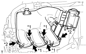
Text in Illustration *1 Bolt *2 Nut Using a 5 mm hexagon socket wrench, install the intake air surge tank assembly with the 4 bolts and 2 nuts.
- Torque:
- Bolt
- 18 N*m { 184 kgf*cm, 13 ft.*lbf }
- Nut
- 16 N*m { 163 kgf*cm, 12 ft.*lbf }
-

Install the throttle body bracket and No. 1 surge tank stay with the 2 bolts.
- Torque:
- 21 N*m { 214 kgf*cm, 15 ft.*lbf }
-
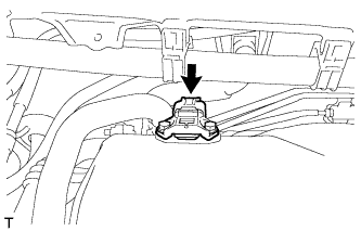
Connect the connector to the manifold absolute pressure sensor.
-
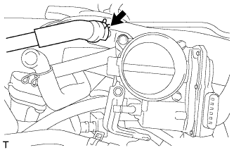
Connect the ventilation hose.
-
Install the 5 clamps and connect the main wire to the body.
-
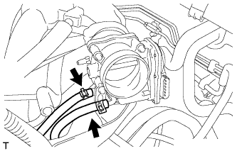
Connect the 2 water by-pass hoses to the throttle body assembly.
-
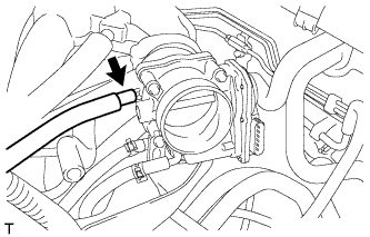
Connect the fuel vapor feed hose.
-
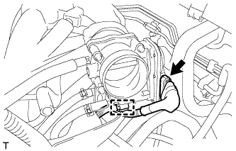
Connect the throttle body assembly connector and wire harness clamp to the throttle body assembly.
-
-
INSTALL ENGINE HANGERS
-
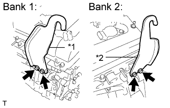
Text in Illustration *1 No. 1 Engine Hanger *2 No. 2 Engine Hanger Install the 2 engine hangers with the 4 bolts as shown in the illustration.
- Torque:
- 33 N*m { 337 kgf*cm, 24 ft.*lbf }
Part No. Item Part No. No. 1 Engine Hanger 12281-31120 No. 2 Engine Hanger 12282-31100 Bolt 91671-10825 -
Attach the engine sling device and hang the engine with the chain block.
-
-
REMOVE ENGINE STAND
-
Remove the engine assembly from the engine stand.
-