ENGINE ASSEMBLY INSTALLATION

-
INSTALL FLYWHEEL SUB-ASSEMBLY
-
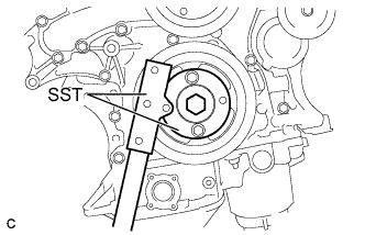
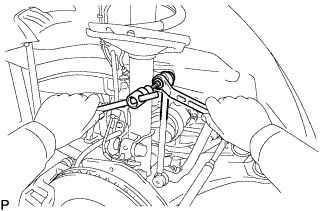
Using SST, hold the crankshaft pulley.
- SST
- 09213-70011 ( 09213-70020 )
- 09330-00021
-
Clean the 8 bolts and 8 bolt holes.
-
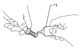
Text in Illustration *1 Adhesive Apply adhesive to 2 or 3 threads of the 8 bolts.
Adhesive Toyota Genuine Adhesive 1324, Three Bond 1324 or equivalent -
Install the flywheel sub-assembly.
-
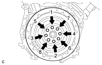
In several steps, uniformly install and tighten the 8 bolts in the sequence shown in the illustration.
- Torque:
- 83 N*m { 846 kgf*cm, 61 ft.*lbf }
Note
Do not start the engine within 1 hour after installing.
-
-
INSTALL TRANSMISSION INPUT DAMPER ASSEMBLY
-
Using SST, hold the crankshaft pulley.
- SST
- 09213-70011 ( 09213-70020 )
- 09330-00021
-
Install the transmission input damper.
-
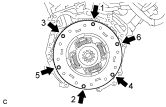
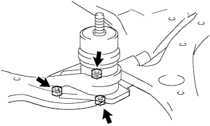
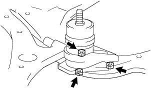
In several steps, uniformly install and tighten the 6 bolts in the sequence shown in the illustration.
- Torque:
- 30 N*m { 306 kgf*cm, 22 ft.*lbf }
Note
Take care not to insert the transmission input damper in a wrong direction.
-
-
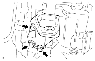
INSTALL REAR ENGINE MOUNTING BRACKET
-
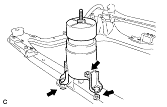
Install the rear engine mounting bracket with the 3 bolts.
- Torque:
- 64 N*m { 652 kgf*cm, 47 ft.*lbf }
-
-
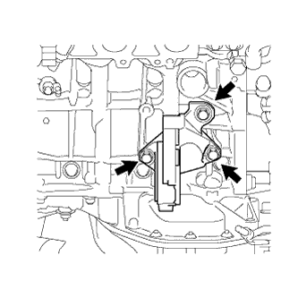
INSTALL ELECTRIC INVERTER COMPRESSOR ASSEMBLY
-
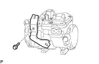
Install the bracket with the bolt to the electric inverter compressor assembly.
-
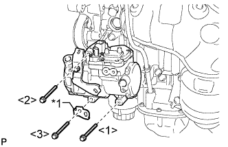
Text in Illustration *1 Bracket Install the electric inverter compressor assembly and bracket with the 3 bolts.
- Torque:
- 25 N*m { 250 kgf*cm, 18 ft.*lbf }
Note
Tighten the bolts in the order shown in the illustration to install the electric inverter compressor assembly.
-
-
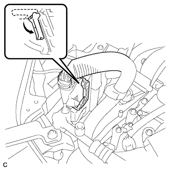
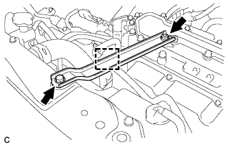
INSTALL V-RIBBED BELT
-
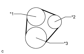
Text in Illustration *1 Water Pump *2 Idler *3 Crankshaft Install the V-ribbed belt.
-
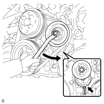
Turn the V-ribbed belt tensioner counterclockwise and remove a 5 mm bi-hexagon wrench.
-
After installing the V-ribbed belt, check that it fits properly in the ribbed grooves. Confirm that the belt has not slipped out of the grooves on the bottom of the crank pulley by hand.
-
-
INSTALL ENGINE MOUNTING BRACKET RH
-
Install the engine mounting bracket RH with the 3 bolts.
- Torque:
- 54 N*m { 551 kgf*cm, 40 ft.*lbf }
-
-
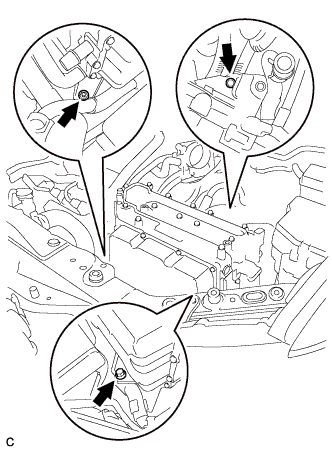
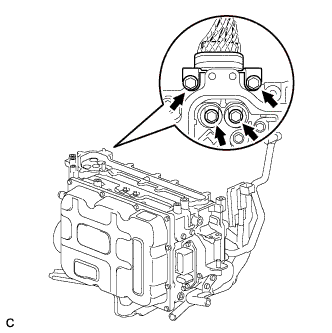
INSTALL HYBRID VEHICLE TRANSAXLE ASSEMBLY
-
Make sure that the knock pins are installed on the engine.
-
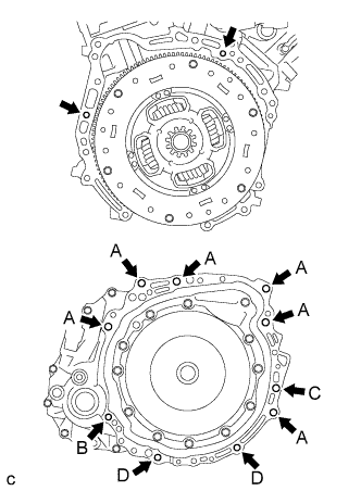
Install the hybrid vehicle transaxle with the 10 bolts shown in the illustration to the engine.
- Torque:
- Bolt A
- 64 N*m { 653 kgf*cm, 47 ft.*lbf }
- Torque:
- Bolt B
- 46 N*m { 469 kgf*cm, 34 ft.*lbf }
- Torque:
- Bolt C
- 64 N*m { 653 kgf*cm, 47 ft.*lbf }
- Torque:
- Bolt D
- 43 N*m { 438 kgf*cm, 32 ft.*lbf }
Note
-
Do not reuse bolt B.
-
Do not forcibly pry on the hybrid vehicle transaxle assembly.
-
Do not apply grease either to the splines or to the input shaft.
Bolt Installation Direction Diameter Bolt Length A From transaxle to engine 12 mm (0.472 in.) 55 mm (2.17 in.) B From engine to transaxle 10 mm (0.393 in.) 41 mm (1.61 in.) C From transaxle to engine 12 mm (0.472 in.) 65 mm (2.55 in.) D From engine to transaxle 10 mm (0.393 in.) 33 mm (1.30 in.)
-
-
INSTALL FRONT ENGINE MOUNTING BRACKET
-
Install the front engine mounting bracket with the 3 bolts.
- Torque:
- 64 N*m { 653 kgf*cm, 47 ft.*lbf }
-
-
INSTALL AUTOMATIC TRANSMISSION CASE COVER
-
Install the automatic transmission case cover with the 2 bolts.
- Torque:
- 7.0 N*m { 71 kgf*cm, 62 in.*lbf }
-
-
INSTALL NO. 3 AUTOMATIC TRANSMISSION CASE COVER
-
Install the No. 3 automatic transmission case cover with the 2 bolts and clip.
- Torque:
- 8.4 N*m { 85 kgf*cm, 74 in.*lbf }
-
Install the No. 3 transmission control cable bracket with the bolt.
- Torque:
- 12 N*m { 122 kgf*cm, 9 ft.*lbf }
-
-
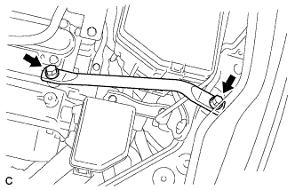
INSTALL MANIFOLD STAY
-
Install the manifold stay with the bolt and nut.
- Torque:
- Bolt
- 34 N*m { 347 kgf*cm, 25 ft.*lbf }
- Nut
- 35 N*m { 357 kgf*cm, 26 ft.*lbf }
-
-
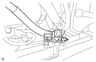
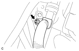
INSTALL RADIATOR PIPE CLAMP
-
Install the radiator pipe clamp with the bolt.
- Torque:
- 5.5 N*m { 56 kgf*cm, 49 in.*lbf }
-
Install the sensor wire and the breather plug hose to the radiator pipe clamp.
-
-
INSTALL ENGINE WIRE
-
Install the engine wire to the engine with transaxle.
-
-
INSTALL FRONT ENGINE MOUNTING INSULATOR
-
Install the front engine mounting insulator with the 3 nuts.
- Torque:
- 52 N*m { 530 kgf*cm, 38 ft.*lbf }
Tech Tips
Perform this procedure only when replacement of the front engine mounting insulator is necessary.
-
Install the 2 hole plugs.
-
-
INSTALL ENGINE MOUNTING INSULATOR LH
-
Install the engine mounting insulator LH with the 3 nuts.
- Torque:
- 87 N*m { 887 kgf*cm, 64 ft.*lbf }
Tech Tips
Perform this procedure only when replacement of the engine mounting insulator LH is necessary.
-
Install the 2 hole plugs.
-
-
INSTALL ENGINE MOUNTING INSULATOR RH
-
Install the engine mounting insulator RH with the 3 nuts.
- Torque:
- 87 N*m { 887 kgf*cm, 64 ft.*lbf }
Tech Tips
Perform this procedure only when replacement of the engine mounting insulator RH is necessary.
-
Install the 2 hole plugs.
-
-
INSTALL REAR ENGINE MOUNTING INSULATOR ASSEMBLY
-
Install the rear engine mounting insulator assembly with the 2 nuts.
- Torque:
- 52 N*m { 530 kgf*cm, 38 ft.*lbf }
Tech Tips
Perform this procedure only when replacement of the rear engine mounting insulator assembly is necessary.
-
Install the 2 hole plugs.
-
-
INSTALL FRONT FRAME ASSEMBLY
-
Install the engine mounting insulators RH and LH with the 2 nuts.
- Torque:
- 95 N*m { 969 kgf*cm, 70 ft.*lbf }
-
Install the HV transaxle mass damper with the bolt.
- Torque:
- 14 N*m { 138 kgf*cm, 10 ft.*lbf }
-
Install the front engine mounting insulator with the nut.
- Torque:
- 87 N*m { 887 kgf*cm, 64 ft.*lbf }
-
Install the rear engine mounting insulator assembly with the 2 bolts.
- Torque:
- 75 N*m { 765 kgf*cm, 55 ft.*lbf }
-
Connect the engine wire with the 2 clamps.
-
-
INSTALL ENGINE ASSEMBLY WITH TRANSAXLE
-
Set the engine assembly with transaxle on the engine lifter.
Note
-
Install a height adjustment attachment and plate lift attachment onto the engine assembly with transaxle.
-
Do not position a height adjustment attachment or plate lift attachment onto the front frame assembly.
Tech Tips
Place the engine on wooden blocks or equivalents so that the engine is level.
-
-
Text in Illustration *1 No. 1 Engine Hanger *2 No. 2 Engine Hanger Remove the 4 bolts and 2 engine hangers.
-
Install the engine assembly with transaxle to the vehicle.
Note
Do not raise the engine more than necessary. If the engine is raised excessively, the vehicle may also be lifted up.
Tech Tips
-
Make sure that the engine is clear of all wiring and hoses.
-
While raising the engine into the vehicle, do not allow it to contact the vehicle.
-
-
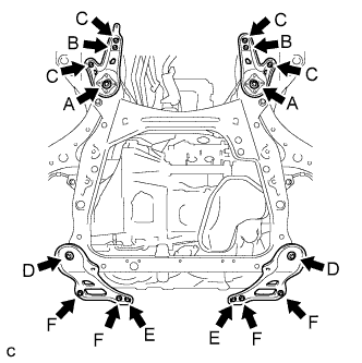
Install the front suspension member rear braces RH and LH with the 6 bolts and 2 nuts.
- Torque:
- Bolt A
- 85 N*m { 867 kgf*cm, 62 ft.*lbf }
- Nut B
- 32 N*m { 326 kgf*cm, 24 ft.*lbf }
- Bolt C
- 32 N*m { 326 kgf*cm, 24 ft.*lbf }
-
Install the frame side rail plates RH and LH with the 6 bolts and 2 nuts.
- Torque:
- Bolt D
- 85 N*m { 867 kgf*cm, 62 ft.*lbf }
- Nut E
- 32 N*m { 326 kgf*cm, 24 ft.*lbf }
- Bolt F
- 32 N*m { 326 kgf*cm, 24 ft.*lbf }
-
w/ Active Stabilizer System:
-

Connect the 2 clamps.
-
Connect the 2 front active stabilizer connectors.
-
-
-
INSTALL HEATER COVER (w/ Active Stabilizer System)
-
Install the heater cover with the 2 bolts.
- Torque:
- 9.8 N*m { 100 kgf*cm, 87 in.*lbf }
-
Connect the clamp.
-
-
INSTALL FLYWHEEL HOUSING UNDER COVER
-
Install the flywheel housing under cover with the 2 bolts.
- Torque:
- 10 N*m { 102 kgf*cm, 7 ft.*lbf }
-
-
INSTALL NO. 1 EXHAUST PIPE SUPPORT BRACKET
-
Install the No. 1 exhaust pipe support bracket with the 2 nuts.
- Torque:
- 21 N*m { 214 kgf*cm, 15 ft.*lbf }
-
-
INSTALL FRONT DRIVE SHAFT HOLE SNAP RING
-
Install a new front drive shaft hole snap ring.
-
-
INSTALL FRONT DRIVE SHAFT ASSEMBLY LH
-
Align the shaft splines and install the drive shaft assembly LH with a brass bar and a hammer.
Note
-
Set the shaft snap ring with the opening facing down.
-
Be careful not to damage the drive shaft dust cover, boot or oil seal.
-
When inserting the drive shaft assembly, keep it level.
-
-
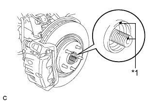
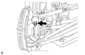
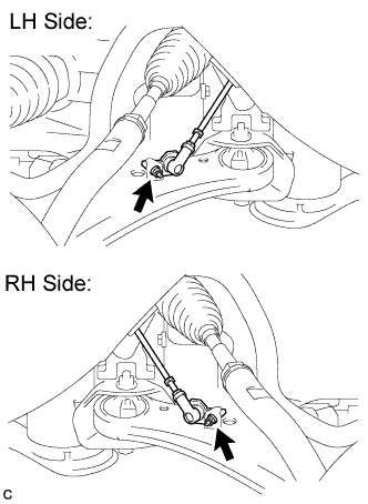
Text in Illustration *1 Matchmark Align the matchmarks and install the front drive shaft assembly LH to the front axle hub sub-assembly.
-
-
INSTALL FRONT DRIVE SHAFT ASSEMBLY RH
-
Install the front drive shaft assembly RH.
-
Install a new bearing bracket hole snap ring and the bolt.
- Torque:
- 32 N*m { 330 kgf*cm, 24 ft.*lbf }
Note
-
Do not damage the boot or oil seal.
-
When inserting the drive shaft assembly, keep it level.
-
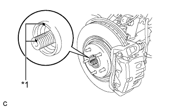
Text in Illustration *1 Matchmark Align the matchmarks and install the front drive shaft assembly RH to the front axle hub sub-assembly.
-
-
INSTALL FRONT LOWER SUSPENSION ARM LH
-
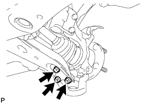
Install the front lower suspension arm to the front lower ball joint with the bolt and 2 nuts.
- Torque:
- 92 N*m { 938 kgf*cm, 68 ft.*lbf }
-
-
INSTALL FRONT LOWER SUSPENSION ARM RH
Tech Tips
Perform the same procedure as for the LH side.
-
INSTALL FRONT STABILIZER LINK ASSEMBLY LH
-
Install the front stabilizer link assembly to the front shock absorber with the nut.
- Torque:
- 74 N*m { 755 kgf*cm, 55 ft.*lbf }
Tech Tips
If the ball joint turns together with the nut, use a hexagon wrench (6 mm) to hold the stud bolt.
-
-
INSTALL FRONT STABILIZER LINK ASSEMBLY RH
Tech Tips
Perform the same procedure as for the LH side.
-
CONNECT TIE ROD ASSEMBLY LH
-
Connect the tie rod assembly LH to the steering knuckle with the nut.
- Torque:
- 49 N*m { 500 kgf*cm, 36 ft.*lbf }
-
Install a new cotter pin.
Note
Further tighten the nut up to 60° if the holes for the cotter pin are not aligned.
-
-
CONNECT TIE ROD ASSEMBLY RH
Tech Tips
Perform the same procedure as for the LH side.
-
INSTALL FRONT SPEED SENSOR LH
-
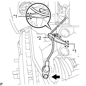
Text in Illustration *1 Hole *2 Resin Clamp Install the resin clamp and front speed sensor with the bolt.
- Torque:
- 8.5 N*m { 87 kgf*cm, 75 in.*lbf }
Note
-
Prevent foreign matter from attaching to the sensor tip.
-
Firmly insert the sensor body into the knuckle before tightening the bolt.
-
After installing the sensor to the knuckle, make sure that there is no clearance between the sensor stay and knuckle. Also make sure that no foreign matter is stuck between the parts.
-
To prevent interference between the sensor and magnetic rotor, do not rotate the sensor body during or after the insertion of the sensor body to the knuckle.
-
-
INSTALL FRONT SPEED SENSOR RH
Tech Tips
Perform the same procedure as for the LH side.
-
INSTALL FRONT AXLE SHAFT NUT LH
-
Clean the threaded parts on the drive shaft and a new axle shaft nut using a non-residue solvent.
Tech Tips
-
Be sure to perform this work for a new drive shaft.
-
Keep the threaded parts free of oil and foreign objects.
-
-
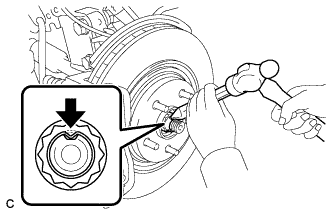
Using a socket wrench (30 mm), install the axle shaft nut.
- Torque:
- 294 N*m { 2998 kgf*cm, 217 ft.*lbf }
-
Using a chisel and hammer, stake the front axle shaft nut.
-
-
INSTALL FRONT AXLE SHAFT NUT RH
Tech Tips
Perform the same procedure as for the LH side.
-
INSTALL HEIGHT CONTROL SENSOR LINK SUB-ASSEMBLY (w/ Air Suspension)
-
Install the height control sensor link sub-assembly LH and RH with the 2 nuts.
- Torque:
- 5.4 N*m { 55 kgf*cm, 48 in.*lbf }
-
-
CONNECT STEERING INTERMEDIATE SHAFT ASSEMBLY
-
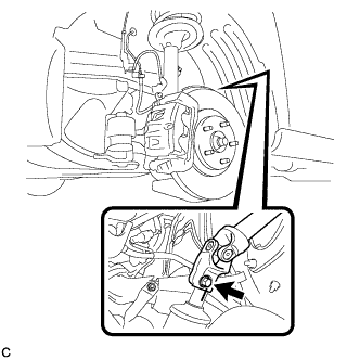
Align the matchmarks on the steering intermediate shaft assembly and steering link assembly.
-
Install the bolt.
- Torque:
- 35 N*m { 360 kgf*cm, 26 ft.*lbf }
-
-
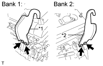
INSTALL FRONT EXHAUST PIPE ASSEMBLY
-
Install a new gasket to the front exhaust pipe assembly.
-
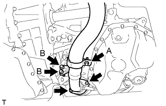
Install the front exhaust pipe assembly with the 2 nuts and 2 bolts (B).
- Torque:
- Bolt B
- 21 N*m { 214 kgf*cm, 15 ft.*lbf }
- Nut
- 55 N*m { 561 kgf*cm, 40 ft.*lbf }
-
Tighten the bolt (A).
- Torque:
- Bolt A
- 21 N*m { 214 kgf*cm, 15 ft.*lbf }
-
Connect the 2 clamps and No. 2 oxygen sensor connector (for Bank 2 Sensor 2).
-
-
INSTALL FRONT NO. 3 EXHAUST PIPE SUB-ASSEMBLY
-
Install 2 new gaskets to the front No. 3 exhaust pipe sub-assembly.
-
Install the front No. 3 exhaust pipe sub-assembly with the 2 bolts and 2 nuts.
- Torque:
- Bolt
- 55 N*m { 561 kgf*cm, 40 ft.*lbf }
- Nut
- 55 N*m { 561 kgf*cm, 40 ft.*lbf }
-
-
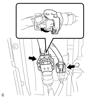
CONNECT FUEL MAIN TUBE
-
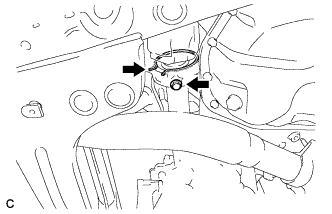
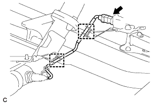
Push in the fuel tube connector to the fuel main tube until the fuel tube connector makes a "click" sound.
Note
-
Check that there is no damage or foreign objects on the fuel tube connector.
-
After connecting, check that the fuel tube connector and the pipe are securely connected by pulling on them.
-
-
Install the No. 1 EFI fuel pipe clamp.
Tech Tips
The half connection prevention connector prevents the fuel hose connector cover from being locked if the fuel tube is not securely connected.
-
-
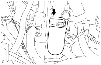
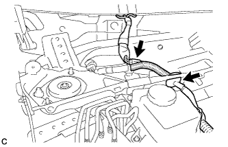
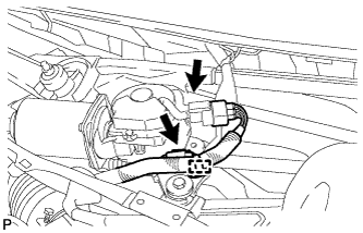
CONNECT DISCHARGE HOSE SUB-ASSEMBLY
-
Remove the attached vinyl tape from the hose.
-
Apply sufficient compressor oil to a new O-ring.
Compressor oil ND-OIL 8 or equivalent -
Install the O-ring onto the discharge hose sub-assembly.
-
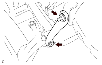
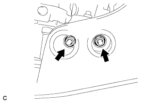
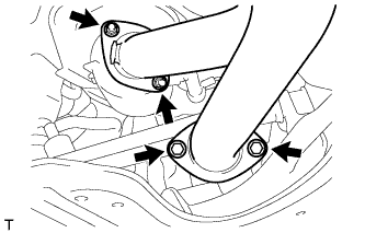
Connect the discharge hose sub-assembly with the nut.
- Torque:
- 9.8 N*m { 100 kgf*cm, 87 in.*lbf }
Note
Be sure to hold the discharge hose while tightening the nut so that the discharge hose is not deformed.
-
-
CONNECT SUCTION HOSE SUB-ASSEMBLY
-
Remove the attached vinyl tape from the hose.
-
Apply sufficient compressor oil to a new O-ring.
Compressor oil ND-OIL 8 or equivalent -
Install the O-ring onto the suction hose sub-assembly.
-
Connect the suction hose sub-assembly with the nut.
- Torque:
- 9.8 N*m { 100 kgf*cm, 87 in.*lbf }
Note
Be sure to hold the suction hose while tightening the nut so that the suction hose is not deformed.
-
-
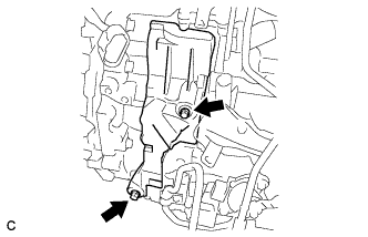
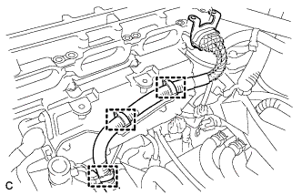
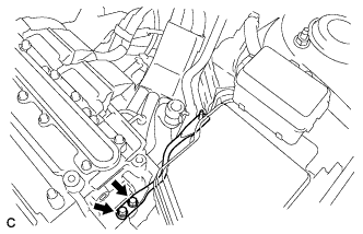
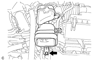
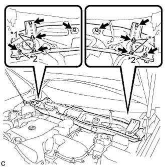
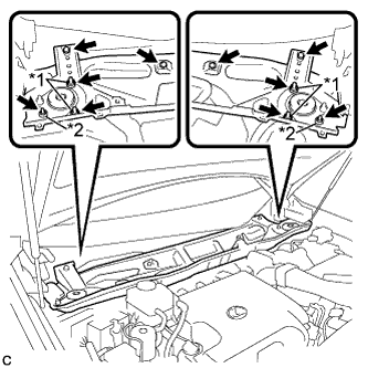
INSTALL ENGINE MOVING CONTROL ROD
-
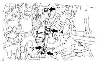
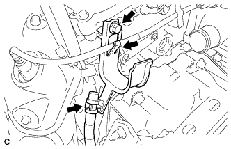
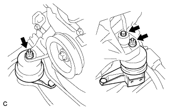
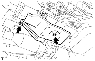
Text in Illustration *1 Bolt A *2 Bolt B *3 Bolt C *4 Bolt D Temporarily install the engine moving control rod and engine mounting control bracket with the bolt A and bolt B.
-
Install the engine mounting control bracket with the bolt C and bolt D.
- Torque:
- 38 N*m { 387 kgf*cm, 28 ft.*lbf }
-
Install the engine moving control rod and engine mounting control bracket with the bolt A and bolt B.
- Torque:
- 38 N*m { 387 kgf*cm, 28 ft.*lbf }
-
-
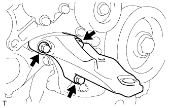
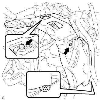
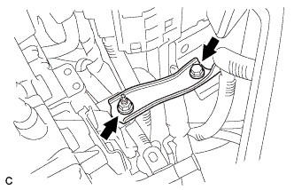
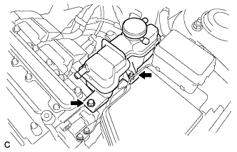
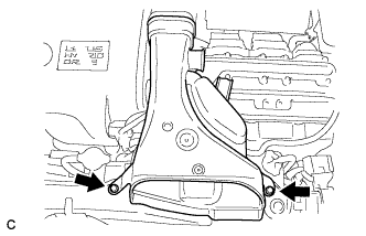
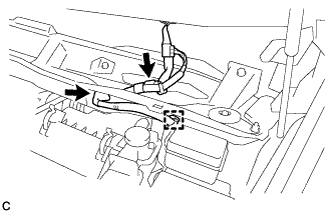
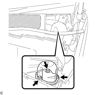
INSTALL NO. 2 ENGINE MOUNTING STAY RH
-
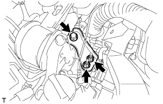
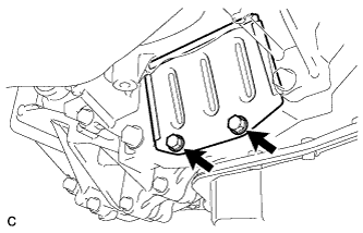
Install the No. 2 engine mounting stay RH with the bolt and 2 nuts.
- Torque:
- Bolt
- 38 N*m { 387 kgf*cm, 28 ft.*lbf }
- Nut
- 23 N*m { 235 kgf*cm, 17 ft.*lbf }
-
-
CONNECT ENGINE WIRE
-
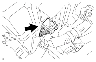
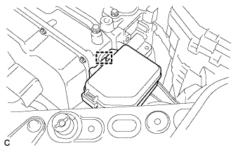
Connect the connector to the ECU to lock the lever.
-
Install the earth wire with the bolt.
- Torque:
- 12 N*m { 122 kgf*cm, 9 ft.*lbf }
-
Connect the 3 clamps.
-
Connect the 3 wire connectors.
-
Install the relay block cover to the relay block.
-
-
INSTALL TRANSMISSION CONTROL CABLE ASSEMBLY
Note
Before installing the transmission control cable, check that the shift lever and neutral start switch are both in the N position.
-
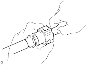
Fold back the boot on the transmission control cable assembly.
-
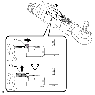
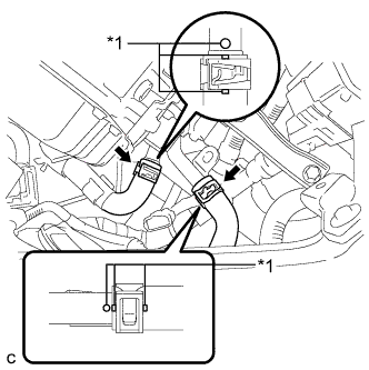
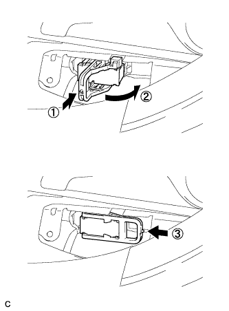
Text in Illustration *1 Slider *2 Lock Piece Move the slider of the transmission control cable assembly as shown in the illustration to raise the lock piece.
-
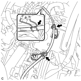
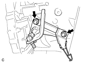
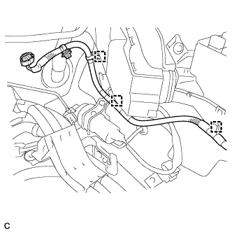
Install the transmission control cable assembly to the 3 control cable brackets.
-
Install a new clip to the control cable bracket.
-
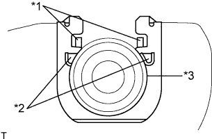
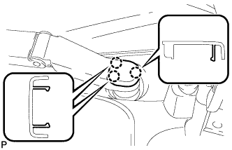
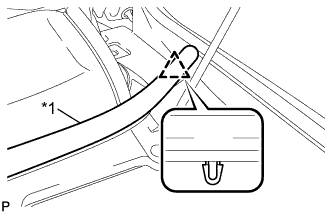
Text in Illustration *1 Claw (A) *2 Claw (B) *3 Control Cable Install the control cable to the control cable bracket.
Note
-
Make sure that the claws (A) on the clip are securely fit into the bracket holes.
-
Make sure that the cable is securely installed inside of the claws (B) of the clip.
-
-
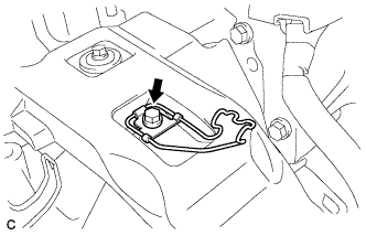
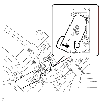
Move the control shaft lever to the N position.
-
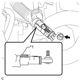
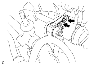
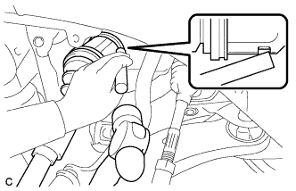
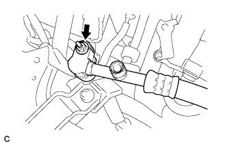
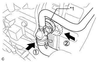
Text in Illustration *1 Lock Piece Connect the transmission control cable assembly to the control shaft lever with the nut.
- Torque:
- 12 N*m { 122 kgf*cm, 9 ft.*lbf }
Note
Check that the lock piece is protruding.
-
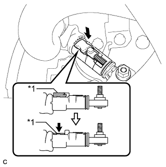
Text in Illustration *1 Lock Piece Press in the lock piece of the transmission control cable assembly.
Note
Be sure to press the lock piece in until the lock of the slider is engaged.
-
Put the boot back on the transmission control cable assembly.
-
-
CONNECT NO. 1 FUEL VAPOR FEED HOSE
-
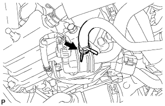
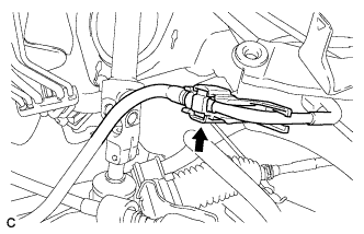
Connect the No. 1 fuel vapor feed hose.
-
-
CONNECT OUTLET HEATER WATER HOSE
-
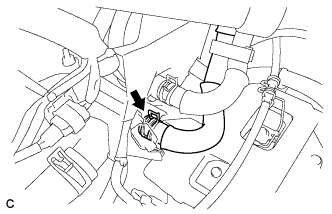
Connect the outlet heater water hose.
-
-
CONNECT INLET HEATER WATER HOSE
-
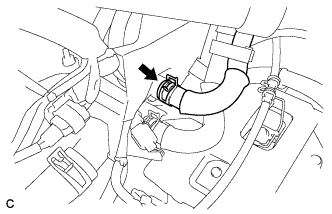
Connect the inlet heater water hose.
-
-
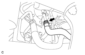
CONNECT NO. 1 RADIATOR HOSE
-
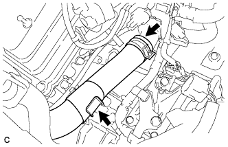
Connect the No. 1 radiator hose.
-
Install the No. 1 radiator hose to the radiator pipe clamp.
-
-
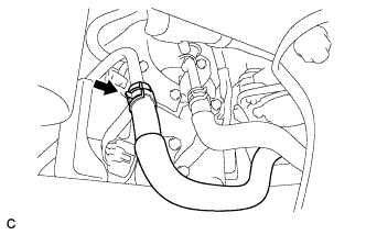
CONNECT NO. 2 RADIATOR HOSE
-
Connect the No. 2 radiator hose.
-
-
CONNECT NO. 3 MOTOR COOLING HOSE
-
Connect the No. 3 motor cooling hose.
-
-
CONNECT NO. 1 MOTOR COOLING HOSE
-
Connect the No. 1 motor cooling hose.
-
-
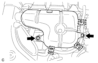
INSTALL INVERTER TRAY BRACKET SUB-ASSEMBLY
-
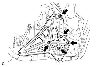
Install the inverter tray bracket sub-assembly with the 5 bolts.
- Torque:
- 17 N*m { 173 kgf*cm, 12 ft.*lbf }
-
-
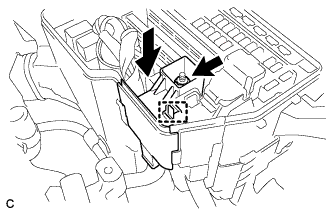
INSTALL INVERTER WITH CONVERTER ASSEMBLY
CAUTION:
Wear insulating gloves.
-
Install the inverter with converter assembly with the 2 bolts and nut.
- Torque:
- 21 N*m { 214 kgf*cm, 15 ft.*lbf }
Note
-
Since the inverter with converter assembly is very heavy, 2 people are needed to remove the inverter with converter assembly. When removing the inverter with converter assembly, do not damage the parts around it.
-
To prevent damage, do not hold the inverter with converter assembly by the connectors.
-
To prevent damage due to static electricity, do not touch the terminals of the disconnected connectors.
-
-
INSTALL CONDENSER
-

Install the condenser with the bolt.
- Torque:
- 8.4 N*m { 86 kgf*cm, 74 in.*lbf }
-
-
INSTALL RADIATOR RESERVE TANK ASSEMBLY
-
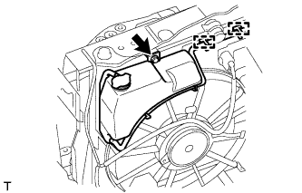
Install the radiator reserve tank with the bolt and connect the 2 clamps to the radiator.
- Torque:
- 5.3 N*m { 54 kgf*cm, 47 in.*lbf }
-
-
INSTALL NO. 4 INVERTER BRACKET
-
Install the No. 4 inverter bracket with the bolt and nut.
- Torque:
- 21 N*m { 214 kgf*cm, 15 ft.*lbf }
-
-
CONNECT NO. 2 ENGINE ROOM WIRE
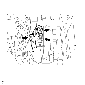
-
Engage the claw and connect the No. 2 engine room wire with the nut.
- Torque:
- 8.4 N*m { 86 kgf*cm, 74 in.*lbf }
-
Connect the clamp.
-
Install the relay block cover.
-
-
CONNECT WATER HOSE
-
Text in Illustration *1 Match Mark Connect the 2 water hoses with the hose clamp to the inverter with converter assembly.
Note
-
Align the match marks of the hoses and pipes.
-
Be sure to insert the hose until it reaches the rib on the pipe.
-
Align the hose clamps to the markings as shown in the illustration.
Tech Tips
Each direction of the hose and hose clamp is indicated in the illustration.
-
-
Text in Illustration *1 Retainer Connect the water hose to the inverter with converter assembly and lock the hose with the retainer.
Note
-
Insert the retainer until a click sound is heard.
-
Pull on the hose to confirm that the hose is securely connected.
-
-
-
CONNECT MG ECU CONNECTOR
Note
-
Make sure that the connectors are fully engaged.
-
Do not allow any foreign objects or water to enter the inverter with converter assembly.
-
Connect the connector to the inverter with converter assembly.
-
Connect the low voltage connector to the inverter with converter assembly and lock the connector with the lock lever.
-
-
INSTALL RELAY BLOCK SUB-ASSEMBLY
-
Install the relay block sub-assembly with the clamp.
-
-
INSTALL NO. 6 INVERTER BRACKET (w/ Bracket)
-
Install the No. 6 inverter bracket with the 2 bolts.
- Torque:
- 21 N*m { 214 kgf*cm, 15 ft.*lbf }
-
-
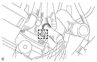
REMOVE INVERTER TERMINAL COVER
-
Remove the 11 bolts and inverter cover from the inverter with converter assembly.
Note
Make sure to pull the inverter cover straight up, as a connector is connected to the bottom of the cover.
-
-
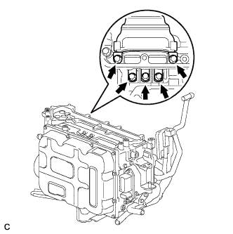
CONNECT NO. 3 WIRE FRAME
CAUTION:
Wear insulating gloves.
Note
-
Make sure that the interlock are fully engaged.
-
Do not allow any foreign objects or water to enter the inverter with converter assembly.
-
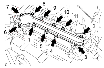
Connect the No. 3 wire frame (high voltage cables of the hybrid battery) with the 4 bolts to the inverter with converter assembly.
- Torque:
- 8.0 N*m { 82 kgf*cm, 71 in.*lbf }
Note
Be sure to use a torque wrench to tighten the bolt.
-
Connect the 3 clamps.
-
-
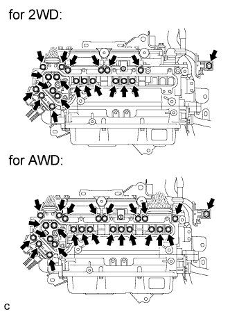
CONNECT HIGH VOLTAGE CABLE OF FRONT MOTOR
CAUTION:
Wear insulating gloves.
Note
Do not allow any foreign objects or water to enter the inverter with converter assembly.
-
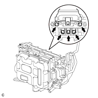
Connect the high voltage cable of the generator (MG1) with the 5 bolts to the inverter with converter assembly.
- Torque:
- 8.0 N*m { 82 kgf*cm, 71 in.*lbf }
-
Connect the high voltage cable of the motor (MG2) with 5 bolts to the inverter with converter assembly.
- Torque:
- 8.0 N*m { 82 kgf*cm, 71 in.*lbf }
-
-
CONNECT NO. 3 WIRE FRAME (for AWD)
CAUTION:
Wear insulating gloves.
Note
Do not allow any foreign objects or water to enter the inverter with converter assembly.
-
Connect the No. 3 wire frame (high voltage cable of the rear motor (MGR)) with 5 bolts to the inverter with converter assembly
- Torque:
- 8.0 N*m { 82 kgf*cm, 71 in.*lbf }
-
Connect the clamp.
-
-
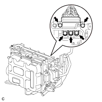
CONNECT NO. 4 ENGINE WIRE
CAUTION:
Wear insulating gloves.
Note
Do not allow any foreign objects or water to enter the inverter with converter assembly.
-
Connect the No. 4 engine wire (high voltage cables of the air conditioning) with the 5 bolts to the inverter with converter assembly
- Torque:
- 8.0 N*m { 82 kgf*cm, 71 in.*lbf }
-
-
CHECK HIGH VOLTAGE CABLE CONNECTION
CAUTION:
Wear insulating gloves.
Note
Do not allow any foreign objects or water to enter the inverter with converter assembly.
-
Check that each connector and terminal is firmly installed.
- Torque:
- for Bolt
- 8.0 N*m { 82 kgf*cm, 71 in.*lbf }
- for Nut
- 8.4 N*m { 86 kgf*cm, 74 in.*lbf }
Note
Make sure that the bolts are fully tightened.
-
-
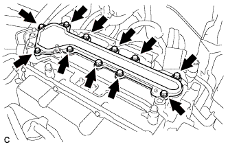
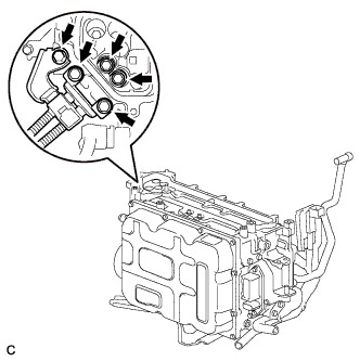
INSTALL INVERTER TERMINAL COVER
CAUTION:
Wear insulating gloves.
Note
-
Make sure that the interlock are fully engaged.
-
Do not allow any foreign objects or water to enter the inverter with converter assembly.
-
Using several steps, install the inverter terminal cover with the 11 bolts uniformly in the sequence shown in the illustration.
- Torque:
- 8.0 N*m { 82 kgf*cm, 71 in.*lbf }
-
-
INSTALL NO. 1 INVERTER RESERVE TANK BRACKET
-
Install the No. 1 inverter reserve tank bracket with the 2 bolts to the inverter with converter assembly.
- Torque:
- 10 N*m { 102 kgf*cm, 7 ft.*lbf }
-
-
INSTALL INVERTER RESERVE TANK ASSEMBLY
-
Install the inverter reserve tank with the bolt and nut to the No. 1 inverter reserve tank bracket.
- Torque:
- 10 N*m { 102 kgf*cm, 7 ft.*lbf }
-

Connect the 3 water hoses to the inverter reserve tank sub-assembly with the 3 hose clamps.
-
Connect the hose to the clamp.
-
-
INSTALL NO. 3 INVERTER BRACKET
-
Install the No. 3 inverter bracket with the 2 bolts.
- Torque:
- 10 N*m { 102 kgf*cm, 7 ft.*lbf }
-
Install the hose clamp to the No. 3 inverter bracket.
-
-
INSTALL AIR CLEANER ASSEMBLY WITH HOSE
-
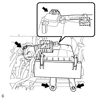
Install the air cleaner assembly with hose with the 2 bolts.
- Torque:
- 5.5 N*m { 56 kgf*cm, 49 in.*lbf }
-
Install the air cleaner hose with the band.
-
Install the No. 1 fuel vapor feed hose to the air cleaner hose.
-
Connect the air flow meter connector and harness clamp.
-
-
INSTALL INLET NO. 1 AIR CLEANER
-
Install the inlet No. 1 air cleaner with the bolt.
- Torque:
- 8.0 N*m { 82 kgf*cm, 71 in.*lbf }
-
Connect the No. 1 fuel vapor feed hose to the clamp.
-
-
INSTALL V-BANK COVER SUB-ASSEMBLY
-
Fit the 4 retainers and install the V-bank cover sub-assembly.
-
-
INSTALL INLET NO. 2 AIR CLEANER
-
Install the inlet No. 2 air cleaner with the 2 bolts.
- Torque:
- 8.0 N*m { 82 kgf*cm, 71 in.*lbf }
-
-
INSTALL INTAKE AIR RESONATOR SUB-ASSEMBLY
-
Install the intake air resonator sub-assembly with the 2 bolts.
- Torque:
- 8.0 N*m { 82 kgf*cm, 71 in.*lbf }
-
Connect the 3 water hose clamps to the intake air resonator sub-assembly.
-
-
INSTALL SERVICE PLUG GRIP
CAUTION:
Wear insulated gloves.
Note
Before connecting the service plug, check that no parts and tools remain and that the high voltage terminals and connectors are connected securely.
-
Wear insulated gloves and insert the service plug grip in the order shown in the illustration.
-
Tilt the service plug grip 90° and slide it down until a click sound is heard.
-
-
INSTALL BATTERY SERVICE HOLE COVER
-
Engage the 2 clips, 2 guides and install the battery service hole cover.
Note
Make sure that the battery service hole cover is installed securely.
-
-
ADD ENGINE OIL
-
Add clean engine oil and install the oil filler cap.
Standard Oil Grade Oil Grade Oil Viscosity (SAE) API grade SL or SM multigrade engine oil
-
20W-50
-
15W-40
-
API grade SL "Energy-Conserving".
-
SM "Energy-Conserving" or ILSAC multigrade engine oil
-
10W-30
-
5W-30
-
5W-20
-
0W-20
Standard Capacity Item Standard Condition Drain and refill with oil filter change 6.1 liters (6.4 US qts, 5.4 lmp. qts) Drain and refill without oil filter change 5.7 liters (6.0 US qts, 5.0 lmp. qts) Dry fill 6.8 liters (7.2 US qts, 6.0 lmp. qts) -
-
-
ADD HYBRID TRANSAXLE FLUID
-
Text in Illustration *1 Filler Nozzle Add transaxle fluid until the transaxle fluid level is between 0 mm (0 in.) from the bottom lip of the filler plug opening.
Note
-
Keep the oil temperature at 5°C (41°F) or higher.
-
Stop the vehicle on a flat road.
-
Recheck the transaxle fluid level after driving following transaxle fluid replacement.
-
Insufficient or excessive amounts of transaxle fluid may be the cause of some trouble.
-
Be sure to add fluid slowly. If fluid is added quickly, the fluid may hit internal parts and bounce back, resulting in fluid coming out of the filler plug opening.
-
Be sure to fully insert the filler nozzle into the filler plug opening.
-
-
Using a hexagon socket wrench 10 mm, temporarily tighten the filler plug and gasket.
-
-
ADD COOLANT (for Engine)
-
Tighten the radiator drain cock plug by hand.
-
Tighten the 2 cylinder block drain cock plugs.
- Torque:
- 13 N*m { 130 kgf*cm, 9 ft.*lbf }
-
Loosen the air drain cock plug on the water inlet housing.
-
Add TOYOTA Super Long Life Coolant (SLLC) to the radiator inlet opening until coolant overflows from the air drain cock hole. Then tighten the air drain cock plug to the water inlet housing.
- Torque:
- 13 N*m { 130 kgf*cm, 9 ft.*lbf }
-
Slowly fill the radiator with TOYOTA Super Long Life Coolant (SLLC).
Standard Capacity Item Capacity Engine coolant 11.7 liters (12.4 US qts, 10.2 lmp. qts) Tech Tips
-
TOYOTA vehicles are filled with TOYOTA SLLC at the factory. In order to avoid damage to the engine cooling system and other technical problems, only use TOYOTA SLLC or similar high quality ethylene glycol based non-silicate, non-amine, non-nitrite, non-borate coolant with long-life hybrid organic acid technology (coolant with long-life hybrid organic acid technology is a combination of low phosphates and organic acids).
-
Contact your TOYOTA dealer for further details.
Note
Never use water as a substitute for engine coolant.
-
-
Text in Illustration *1 Full Line Slowly pour coolant into the radiator reservoir tank until it reaches the full line.
-
Install the radiator cap.
-
Squeeze the No. 1 and No. 2 radiator hoses several times by hand, and then check the level of the coolant.
If the coolant level is low, add coolant.
-
Bleed air from the cooling system.
-
Put the engine in inspection mode Click here.
-
Warm up the engine until the thermostat opens. While the thermostat is open, circulate the coolant for several minutes.
Tech Tips
The thermostat open timing can be confirmed by squeezing the No. 2 radiator hose by hand, and checking when the engine coolant starts to flow inside the hose.
-
Maintain the engine speed at 2500 rpm.
-
Squeeze the inlet and No. 1 and No. 2 radiator hoses several times by hand to bleed air.
CAUTION:
When squeezing the radiator hoses:
-
Wear protective gloves.
-
Be careful as the radiator hoses are hot.
-
Keep your hands away from the cooling fans.
Note
-
Make sure that the radiator reservoir still has some coolant in it.
-
If the coolant temperature gauge indicates an excessive temperature, turn off the engine and let it cool.
-
If there is not enough coolant, the engine may overheat or be seriously damaged.
-
If the radiator reservoir does not have enough coolant, perform the following: 1) stop the engine, 2) wait until the coolant has cooled down, and 3) add coolant until the reservoir is filled to the Full line.
-
-
-
Stop the engine and wait until the engine coolant cools down.
-
Add engine coolant to the full line on the radiator reservoir.
-
-
ADD COOLANT (for Inverter)
Note
-
Do not reuse the drained coolant because it may contain foreign objects.
-
If the vehicle is driven with air in the inverter cooling system, the following DTCs may be set.
DTC Code Detection Item P0A01-726 Motor Electronics Coolant Temperature Sensor Circuit Range / Performance P0A04-725 Motor Electronics Coolant Temperature Sensor Circuit Intermittent P0A08-264 DC / DC Converter Status Circuit P0A78-284 Drive Motor "A" Inverter Performance P0A78-286 Drive Motor "A" Inverter Performance P0A79-692 Drive Motor "B" Inverter Performance P0A79-696 Drive Motor "B" Inverter Performance P0A7A-322 Generator Inverter Performance P0A7A-324 Generator Inverter Performance P0A93-346 Inverter Cooling System Performance P0A94-553 DC / DC Converter Performance P0A94-557 DC / DC Converter Performance P0AEE-277 Motor Inverter Temperature Sensor "A" Circuit Range / Performance P0AF1-276 Drive Motor Inverter Temperature Sensor "A" Circuit Intermittent / Erratic P0AF3-676 Sensor of Rear Motor Inverter Temperature P0AF6-675 Drive Motor Inverter Temperature Sensor "B" Circuit Intermittent / Erratic P0BCD-315 Generator Inverter Temperature Sensor Circuit Range / Performance P0BD0-314 Generator Inverter Temperature Sensor Circuit Intermittent / Erratic P0C39-626 DC / DC Converter Temperature Sensor "A" Range / Performance P0C3C-625 DC / DC Converter Temperature Sensor "A" Intermittent / Erratic P0C3E-628 DC / DC Converter Temperature Sensor "B" Range / Performance P0C41-627 DC / DC Converter Temperature Sensor "B" Intermittent / Erratic P0C73-776 Motor Electronics Coolant Pump "A" Control Performance
-
Add coolant to the reserve tank.
-
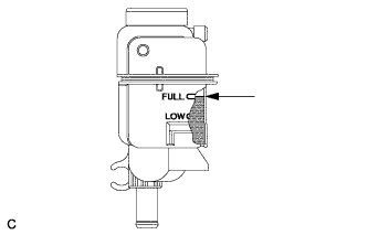
Slowly pour coolant into the radiator reservoir tank until it reaches the FULL line.
Coolant quantity 1.9 liter (2.0 US qts, 1.7 Imp. qts.) -
When using the intelligent tester:
-
Connect the intelligent tester to the DLC3.
-
Turn the power switch on (IG).
-
On the intelligent tester, enter the following menus: Powertrain / Hybrid Control / Active Test / Activate the Water Pump.
-
Keep the coolant at the FULL level in the reserve tank to compensate for the drop in coolant level when the air bleeds.
Standard Air bleeding from the coolant system is completed when the noise made by the water pump becomes smaller and the circulation of coolant in the reserve tank improves. Tech Tips
Loud noise made by the water pump and poor circulation of coolant in the reserve tank indicates that there is air in the coolant system.
-
-
When not using the intelligent tester:
-
Turn the power switch on (READY). [*1]
-
Turn the power switch off and keep the coolant at the FULL level in the reserve tank to compensate for the drop in coolant level when the air bleeds. [*2]
Note
-
Be sure to turn the power switch off before adding SLLC.
-
Do not work on the components in the engine compartment while the vehicle is in the READY-on state because the engine is in intermittent operation.
-
-
Repeat steps [*1] and [*2] until air bleeding from the coolant system is completed.
Standard Air bleeding from the coolant system is completed when the noise made by the water pump becomes smaller and the circulation of coolant in the reserve tank improves. Tech Tips
Loud noise made by the water pump and poor circulation of coolant in the reserve tank indicates that there is air in the coolant system.
-
-
Add coolant to the FULL mark of the reserve tank.
-
-
CONNECT AUXILIARY BATTERY
Note
When disconnecting the cable, some systems need to be initialized after the cable is reconnected Click here.
-
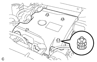
INSTALL REAR DECK FLOOR BOX
-

Install the rear deck floor box with the 3 clips.
-
-
WARM UP ENGINE
-
INSPECT ENGINE OIL LEVEL
-
Warm up and stop the engine, then wait for 5 minutes. The oil level should be between the low level and full level marks on the engine oil level dipstick.
If the engine oil level is low, check for leakage and add oil up to the full level mark.
Note
Do not add engine oil to above the full level mark.
-
-
INSPECT COOLANT LEVEL IN RESERVOIR (for Engine)
-
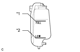
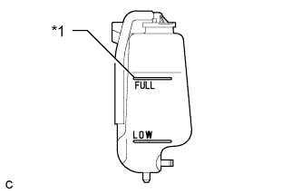
Text in Illustration *1 Full Line *2 Low Line Check that the engine coolant level is between the low and full lines when the engine is cold.
If the engine coolant level is low, check for leaks and add "TOYOTA Super Long Life Coolant" or similar high quality ethylene glycol based non-silicate, non-amine, non-nitrite and non-borate coolant with long-life hybrid organic acid technology to the full line.
Note
Do not substitute plain water for engine coolant.
-
-
INSPECT FOR COOLANT LEAK (for Inverter)
-
Remove the reserve tank cap.
CAUTION:
To avoid the danger of being burned, do not remove the reserve tank cap while the coolant for the inverter is still hot.
-
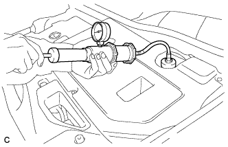
Install the radiator cap tester.
-
Pump the radiator cap tester to 118 kPa (1.2 kgf/ cm2, 17 psi), and then check that the pressure does not drop.
Tech Tips
If the pressure drops, check the hoses, radiator, water pump, inverter with converter, and hybrid vehicle transaxle assembly for leaks.
-
Reinstall the reserve tank cap.
-
-
CHARGE WITH REFRIGERANT
-
Perform vacuum purging using a vacuum pump.
-
Charge with refrigerant HFC-134a (R134a).
Standard 550 to 650 g (19.4 to 22.9 oz.) - SST
- 09985-20010 ( 09985-02010, 09985-02050, 09985-02060, 09985-02070, 09985-02080, 09985-02090, 09985-02110, 09985-02130, 09985-02140, 09985-02150 )
Note
-
Do not turn the A/C on before charging with refrigerant. Doing so will cause the compressor to work without refrigerant, resulting in overheating of the cooler compressor.
-
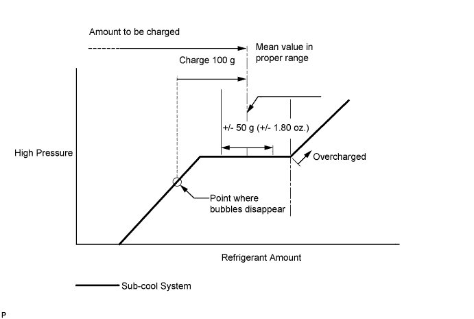
Approximately 100 g (3.53 oz.) of refrigerant may need to be charged after bubbles disappear. The refrigerant amount should be checked by quantity, not with the sight glass.
-
Avoid using the gauge manifold set that had been used for vehicles with conventional compressor oil (ND-OIL 8 or equivalent) as much as possible. This will cause compressor oil remaining in the manifold to enter the vehicle, resulting in insulation performance deterioration. A gauge manifold set that had been used 3 times or less can be reused if an appropriate one is not available.
Tech Tips
Ensure that sufficient refrigerant is available to recharge the system when using a refrigerant recovery unit. Refrigerant recovery units are not always able to recover 100% of the refrigerant from an A/C system.
-
-
INSPECT FOR FUEL LEAK
-
Check fuel pump operation.
-
Connect the intelligent tester to the DLC3.
-
Turn the power switch on (IG).
Note
Do not start the engine.
-
Turn the intelligent tester on.
-
Enter the following menus: Powertrain / Engine / Active Test / Control the Fuel Pump / Speed.
-
Check for pressure in the fuel inlet tube from the fuel line. Check that sounds of fuel flowing from the fuel tank can be heard. If no sounds can be heard, check the integration relay, fuel pump, ECM and wiring connectors.
-
-
Inspect for fuel leaks.
-
Check that there are no fuel leaks from the fuel system after doing any maintenance or repairs. If there is a fuel leak, repair or replace parts as necessary.
-
-
Turn the power switch off.
-
Disconnect the intelligent tester from the DLC3.
-
-
INSPECT FOR COOLANT LEAK (for Engine)
CAUTION:
Do not remove the radiator cap while the engine and radiator are still hot. Pressurized hot engine coolant and steam may be released and cause serious burns.
Note
Before performing each inspection, turn the A/C switch off.
-
Remove the radiator cap.
-
Fill the radiator with coolant and attach a radiator cap tester.
-
Put the engine in inspection mode Click here.
-
Warm up the engine.
-
Using the radiator cap tester, increase the pressure inside the radiator to 118 kPa (1.2 kgf/cm2, 17 psi), and check that the pressure does not drop.
If the pressure drops, check the hoses, radiator, exhaust center pipe assembly and the heater hose around the water temperature switch and engine water pump for leaks. If no external leaks are found, check the heater core, cylinder block and cylinder head.
-
Remove the radiator cap tester.
-
Install the radiator cap.
-
-
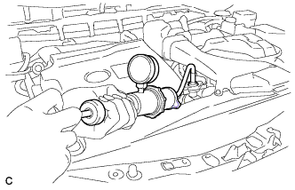
INSPECT AND ADJUST HYBRID TRANSAXLE FLUID
-
Set the vehicle to FWD inspection mode Click here.
-
After waiting for 1 minute or more, stop the engine.
-
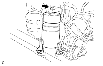
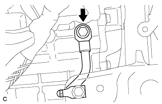
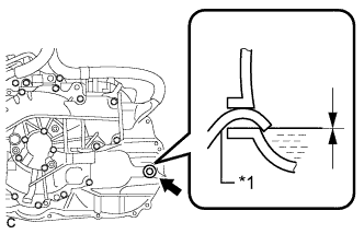
Text in Illustration *1 Filler Plug Using a hexagon socket wrench 10 mm, remove the filler plug and gasket.
-
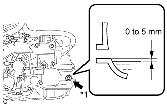
Add transaxle fluid until the transaxle fluid level is between 0 and 5 mm (0 and 0.197 in.) from the bottom lip of the filler plug opening.
Note
-
Keep the transaxle fluid temperature at 5°C (41°F) or higher.
-
Stop the vehicle on a flat road.
-
Recheck the transaxle fluid level after driving following transaxle fluid replacement.
-
Insufficient or excessive amounts of transaxle fluid may be the cause of some trouble.
-
Be sure to add fluid slowly. If fluid is added quickly, the fluid may hit internal parts and bounce back, resulting in fluid coming out of the filler plug opening.
-
Be sure to directly check that the transaxle fluid level is within the specified range.
-
-
After adding fluid, leave it for 30 seconds so that the fluid surface can become still again, and then check that the fluid level is between 0 to 5 mm (0 to 0.197 in.) from the bottom lip of the filler plug opening. (If the fluid is insufficient, return to the Add Hybrid Transaxle Fluid procedure.)
-
Check for leaks if the quantity of transaxle fluid is low.
-
Using a hexagon socket wrench 10 mm, install the filler plug and a new gasket.
- Torque:
- 39 N*m { 398 kgf*cm, 29 ft.*lbf }
-
-
INSPECT FOR OIL LEAK
-
INSPECT FOR REFRIGERANT LEAK
-
After recharging with refrigerant, inspect for refrigerant leaks using a halogen leak detector.
-
Carry out the test under the following conditions:
-
Turn the power switch off.
-
Secure good ventilation (the halogen leak detector may react to volatile gases which are not refrigerant, such as evaporated gasoline and exhaust gas).
-
Repeat the test 2 or 3 times.
-
Make sure that there is some refrigerant remaining in the refrigeration system.
When the compressor is off: approx. 392 to 588 kPa (4 to 6 kgf/cm2, 57 to 85 psi)
-
-
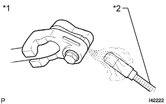
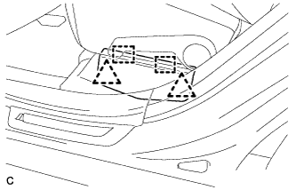
Text in Illustration *1 Inspect for Leak *2 Halogen Leak Detector Using a halogen leak detector, inspect for refrigerant leaks from the refrigerant lines.
-
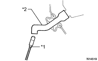
Text in Illustration *1 Halogen Leak Detector *2 Drain Hose Bring the halogen leak detector close to the drain hose with the detector's power off, and then turn the detector on.
Tech Tips
-
After the blower motor has stopped, let the cooling unit stand for more than 15 minutes.
-
Bring the halogen leak detector sensor under the drain hose.
-
When bringing the halogen leak detector close to the drain hose, make sure that the halogen leak detector does not react to volatile gases. If it is not possible to avoid interference from volatile gases, the vehicle should be lifted up to allow testing.
-
-
If a refrigerant leak is not detected from the drain hose, remove the blower motor control from the cooling unit. Insert the halogen leak detector sensor into the unit and perform the test.
-
Disconnect the pressure switch connector and leave it for approximately 20 minutes. Bring the halogen leak detector close to the pressure switch and perform the test.
-
-
INSPECT FOR EXHAUST GAS LEAK
-
INSTALL FRONT FENDER APRON SEAL LH
-
INSTALL FRONT FENDER APRON SEAL RH
-
INSTALL FRONT FENDER LINER RH
-
INSTALL FRONT FENDER LINER LH
-
INSTALL NO. 2 ENGINE UNDER COVER
-
INSTALL NO. 1 ENGINE UNDER COVER
-
INSTALL FRONT WHEEL
- Torque:
- 103 N*m { 1050 kgf*cm, 76 ft.*lbf }
-
PLACE FRONT WHEELS FACING STRAIGHT AHEAD
-
INSPECT SHIFT LEVER POSITION
-
When moving the shift lever from P to R with the power switch on (IG) and the brake pedal depressed, make sure that the shift lever moves smoothly and correctly into position.
-
Turn the power switch on (READY) and make sure that the vehicle moves forward when moving the shift lever from N to D and moves rearward when moving the shift lever to R.
If the operation cannot be performed as specified, inspect the shift lever position sensor and check the shift lever assembly installation condition.
-
-
INSPECT AND ADJUST FRONT WHEEL ALIGNMENT
Tech Tips
-
INSPECT IGNITION TIMING
-
Put the engine in inspection mode Click here.
-
Warm up and stop the engine.
Tech Tips
A warmed up engine should have an engine coolant temperature of over 80°C (176°F), an engine oil temperature of 60°C (140°F), and the engine speed should be stabilized.
-
Put the engine in inspection mode Click here.
-
When using the intelligent tester:
Check the ignition timing.
-
Connect the intelligent tester to the DLC3.
-
Start the engine and run it at idle.
-
Turn the intelligent tester on.
-
Enter the following menus: Powertrain / Engine / Data List / IGN Advance.
Standard ignition timing 0 to 20° BTDC at idle Note
-
Check the ignition timing with the cooling fans off.
-
Turn off all the electrical systems and the A/C.
-
When checking the ignition timing, the transaxle should be in neutral or park.
Tech Tips
Refer to the intelligent tester operator's manual for further details.
-
-
Check that the ignition timing advances immediately when the engine speed is increased.
-
Enter the following menus: Powertrain / Engine / Active Test / Connect the TC and TE1.
-
Monitor IGN Advance of the Data List.
-
Perform the Active Test.
Standard ignition timing 8 to 12° BTDC at idle Note
-
Check the ignition timing with the cooling fans off.
-
Turn off all the electrical systems and the A/C.
-
When checking the ignition timing, the transaxle should be in neutral or park.
Tech Tips
Refer to the intelligent tester operator's manual for further details.
-
-
-
When not using the intelligent tester:
-
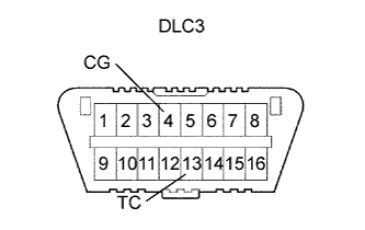
Using SST, connect terminals 13 (TC) and 4 (CG) of the DLC3.
- SST
- 09843-18040
Note
-
Confirm the terminal numbers before connecting them. Connecting the wrong terminals can damage the engine.
-
Check the ignition timing with the cooling fans off.
-
Turn off all the electrical systems and the A/C.
-
When checking the ignition timing, the transaxle should be in neutral or park.
-
Remove the engine room side cover Click here.
-
Remove the engine room side cover LH Click here.
-
Remove the cool air intake duct seal Click here.
-
Remove the V-bank cover sub-assembly Click here.
-
Connect the timing light tester probe to the ignition coil wire for No. 1 cylinder.
Note
Use a timing light that detects the primary signal.
-
Check the ignition timing at idle.
Standard ignition timing 8 to 12° BTDC at idle Note
When checking the ignition timing, the transaxle should be in neutral or park.
Tech Tips
Run the engine at 1000 to 1300 rpm for 5 seconds, and then check that the engine rpm returns to idle speed.
-
Disconnect terminals 13 (TC) and 4 (CG) of the DLC3.
-
Check the ignition timing at idle.
Standard ignition timing 0 to 20° BTDC at idle -
Confirm that the ignition timing advances immediately when the engine rpm is increased.
-
Remove the timing light from the engine.
-
Install the V-bank cover sub-assembly Click here.
-
Install the cool air intake duct seal Click here.
-
Install the engine room side cover LH Click here.
-
Install the engine room side cover Click here.
-
-
-
INSPECT ENGINE IDLE SPEED
-
Put the engine in inspection mode Click here.
-
Warm up and stop the engine.
Tech Tips
A warmed up engine should have an engine coolant temperature of over 80°C (176°F), an engine oil temperature of 60°C (140°F), and the engine speed should be stabilized.
-
Put the engine in inspection mode Click here.
-
Check the idle speed.
-
Connect the intelligent tester to the DLC3.
-
Start the engine and run it at idle.
-
Turn the intelligent tester on.
-
Enter the following menus: Powertrain / Engine / Data List / Engine Speed.
-
Read the value displayed on the tester.
Standard Idle Speed Measurement Condition Idle Speed Park Position 850 to 950 rpm Neutral Position 1250 to 1350 rpm Note
-
Check the idle speed with the cooling fans off.
-
Turn off all the electrical systems and the A/C.
-
When checking the idle speed, the transaxle should be in neutral or park.
Tech Tips
-
Refer to the intelligent tester operator's manual for further details.
-
If the speed is not as specified, check the air intake system.
-
-
-
INSPECT CO/HC
Tech Tips
This check determines whether or not the idle CO/HC complies with regulations.
-
Put the engine in inspection mode Click here.
-
Start the engine.
-
Keep the engine speed at 2500 rpm for approximately 180 seconds.
-
Insert the CO/HC meter testing probe at least 40 cm (1.31 ft.) into the tailpipe during idle.
-
Immediately check CO/HC concentration during idle and when running at 2500 rpm.
Tech Tips
When performing the 2 mode (with the engine idling/running at 2500 rpm) test, follow the measurement order determined by applicable local regulations.
If the CO/HC concentration does not comply with the regulations, perform troubleshooting in the order given below.
-
Check the DTCs Click here.
-
See the table below for possible causes, then inspect and correct the applicable causes if necessary.
CO HC Problem Cause Normal High Rough idle
-
Faulty ignitions:
-
Incorrect valve timing
-
Fouled, shorted or improperly gapped plugs
-
Incorrect valve clearance (valve lash adjuster)
-
Leaks in intake or exhaust valves
-
Leaks in cylinders
Low High Rough idle
(Fluctuating HC reading)
-
Vacuum leaks:
-
PCV hoses
-
Intake manifold
-
Throttle body assembly
-
Brake booster line
-
Lean mixture causing misfire
High High Rough idle
(Black smoke from exhaust)
-
Restricted air cleaner filter element sub-assembly
-
Plugged PCV valve
-
Faulty SFI system:
-
Faulty fuel pressure regulator
-
Defective engine coolant temperature sensor
-
Defective mass air flow meter
-
Faulty ECM
-
Faulty injector assemblies
-
Faulty throttle position sensor (built in throttle body assembly)
-
-
-
-
PERFORM INITIALIZATION
Note
When disconnecting the cable, some systems need to be initialized after the cable is reconnected Click here.
-
CHECK VEHICLE HEIGHT (w/ Air Suspension)
Note
If the height control sensor link is removed, check the vehicle height.
-
Change the height control switch from the "NORM" position to the "HIGH" position and back to the "NORM" position.
-
Measure the vehicle height ( Click here).
-
-
ADJUST VEHICLE HEIGHT (w/ Air Suspension)
Note
If the height control sensor has been replaced, be sure to adjust the vehicle height.
-
Adjust the vehicle height ( Click here).
-
-
INSTALL OUTER COWL TOP PANEL SUB-ASSEMBLY (for LHD)
-
Install the outer cowl top panel sub-assembly with the 4 bolts, 4 nuts*1 and 2 nuts*2.
- Torque:
- Nut*1
- 85 N*m { 867 kgf*cm, 63 ft.*lbf }
- Nut*2
- 5.5 N*m { 56 kgf*cm, 49 in.*lbf }
- Bolt
- 5.5 N*m { 56 kgf*cm, 49 in.*lbf }
-
Engage the grommet and clamp.
-
Connect the connector (w/ Windshield Deicer).
-
-
INSTALL OUTER COWL TOP PANEL SUB-ASSEMBLY (for RHD)
-
Install the outer cowl top panel sub-assembly with the 4 bolts, 4 nuts*1 and 2 nuts*2.
- Torque:
- Nut*1
- 85 N*m { 867 kgf*cm, 63 ft.*lbf }
- Nut*2
- 5.5 N*m { 56 kgf*cm, 49 in.*lbf }
- Bolt
- 5.5 N*m { 56 kgf*cm, 49 in.*lbf }
-
Engage the grommet.
-
Connect the connector (w/ Windshield Deicer).
-
-
INSTALL FRONT SHOCK ABSORBER CAP LH (w/ Air Suspension)
-
Install the front shock absorber cap with the 3 nuts.
- Torque:
- 14 N*m { 143 kgf*cm, 10 ft.*lbf }
-
-
INSTALL FRONT SHOCK ABSORBER CAP RH (w/ Air Suspension)
Tech Tips
Perform the same procedure as for the LH side.
-
INSTALL WINDSHIELD WIPER MOTOR AND LINK ASSEMBLY
-
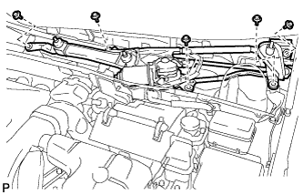
Install the windshield wiper motor and link assembly with the 5 bolts.
- Torque:
- 7.0 N*m { 71 kgf*cm, 62 in.*lbf }
Note
Be careful not to damage the windshield when installing the windshield wiper motor and link assembly.
-
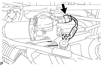
w/o Deicer:
-
Engage the clamp.
-
Connect the connector.
-
-
w/ Deicer:
-
Engage the clamp.
-
Connect each connector.
-
-
-
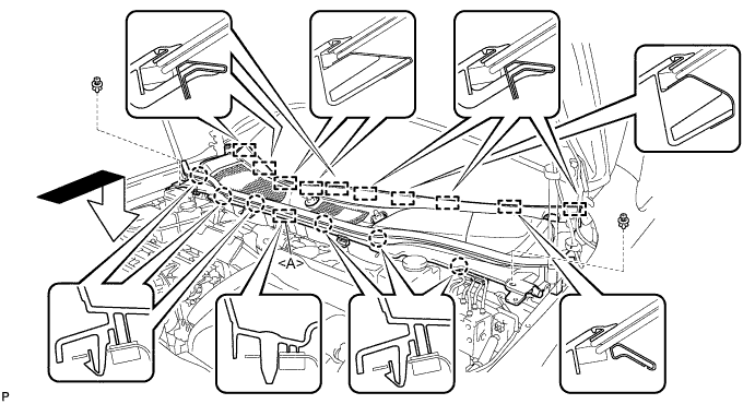
INSTALL COWL TOP VENTILATOR LOUVER SUB-ASSEMBLY
-
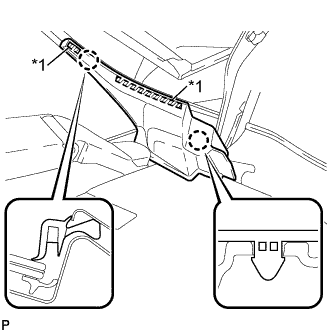
Engage the 10 guides.
-
Engage the 6 claws and guide <A> as shown in the illustration.
-
Install the 2 clips to cowl top ventilator louver sub-assembly.
-
-
INSTALL FRONT WIPER ARM AND BLADE ASSEMBLY RH
-
Operate the wiper and stop the windshield wiper motor at the automatic stop position.
-
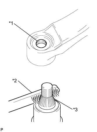
Text in Illustration *1 Wiper Arm Serration *2 Wire Brush *3 Wiper Pivot Serration When reusing the front wiper arm and blade assembly RH:
-
Clean the wiper arm serrations.
-
-
When reusing the windshield wiper link assembly:
-
Clean the wiper pivot serrations with a wire brush.
-
-
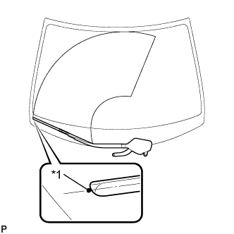
Text in Illustration *1 Ceramic Dot Install the front wiper arm and blade assembly RH with the 2 nuts to the position shown in the illustration.
- Torque:
- 24 N*m { 245 kgf*cm, 18 ft.*lbf }
Tech Tips
While holding the tip of the wiper blade on the glass at approximately 20 mm above the ceramic dot, press down on the wiper arm and tighten the nut. Then raise and lower the wiper arm a few times to confirm that it has settled to the specified position.
-
-
INSTALL FRONT WIPER ARM AND BLADE ASSEMBLY LH
-

Text in Illustration *1 Wiper Arm Serration *2 Wire Brush *3 Wiper Pivot Serration When reusing the front wiper arm and blade assembly LH:
-
Clean the wiper arm serrations.
-
-
When reusing the windshield wiper link assembly:
-
Clean the wiper pivot serrations with a wire brush.
-
-
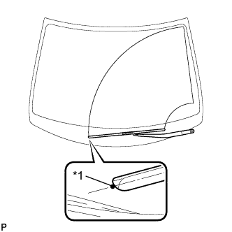
Text in Illustration *1 Ceramic Dot Install the front wiper arm and blade assembly LH with the nut to the position shown in the illustration.
- Torque:
- 24 N*m { 245 kgf*cm, 18 ft.*lbf }
Tech Tips
Hold the wiper arm by hand while tightening the nut.
-
Operate the front wipers while spraying washer fluid on the windshield glass. Make sure that the front wipers function properly and there is no interference with the vehicle body.
-
-
INSTALL FRONT WIPER ARM HEAD CAP
-
Engage the 3 claws to install the front wiper arm head cap.
-
-
INSTALL FRONT FENDER TO COWL SIDE SEAL RH
Tech Tips
Use the same procedure for the RH side and LH side.
-
INSTALL FRONT FENDER TO COWL SIDE SEAL LH
-
Wipe off any tape adhesive residue with cleaner.
-
Text in Illustration *1 Double-sided Tape Engage the 2 claws and install a new front fender to cowl side seal LH.
-
-
INSTALL FRONT FENDER TOP REINFORCEMENT SUB-ASSEMBLY RH
Tech Tips
Use the same procedure for the RH side and LH side.
-
INSTALL FRONT FENDER TOP REINFORCEMENT SUB-ASSEMBLY LH
-
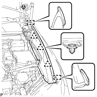
Engage the 3 clips and 2 guides.
-
Install the front fender top reinforcement sub-assembly LH with the clip.
-
Text in Illustration *1 Hood to Cowl Top Seal Engage the clip to the hood to cowl top seal to the front fender top reinforcement sub-assembly LH.
-
-
CHECK FOR SPEED SENSOR SIGNAL
Tech Tips
-
ADJUST HEADLIGHT ASSEMBLY (w/ Air Suspension)
-
Adjust the headlight for HID Headlight Click here.
-
Adjust the headlight for LED Headlight Click here.
-
-
INSTALL COOL AIR INTAKE DUCT SEAL
-
Install the cool air intake duct seal with the 6 clips.
-
-
INSTALL ENGINE ROOM SIDE COVER
-
Install the engine room side cover with the 4 clips.
-
-
INSTALL ENGINE ROOM SIDE COVER LH
-
Install the engine room side cover with the 4 clips.
-