CYLINDER HEAD GASKET INSTALLATION

-
INSTALL CYLINDER HEAD GASKET
-
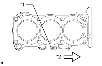
Text in Illustration *1 Lot No. *2 Engine Front Place a new cylinder head gasket on the cylinder block surface with the Lot No. stamp upward.
Note
-
Be careful of the installation direction.
-
Gently lower the cylinder head in order not to damage the gasket with the bottom part of the head.
-
-
-
INSTALL CYLINDER HEAD SUB-ASSEMBLY
-
Place the cylinder head on the cylinder block.
Note
Be careful not to allow oil to adhere to the bottom part of the cylinder head.
Tech Tips
The cylinder head bolts are tightened in 3 progressive steps.
-
Apply a light coat of engine oil to the threads and under the heads of the cylinder head bolts.
-
Step 1
-
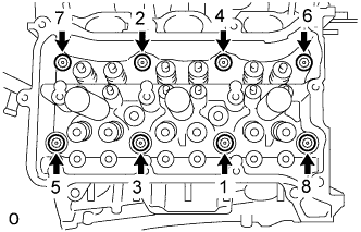
Using a 10 mm bi-hexagon wrench, install and uniformly tighten the 8 cylinder head bolts with the plate washers in several steps and in the sequence shown in the illustration.
- Torque:
- 36 N*m { 367 kgf*cm, 26 ft.*lbf }
-
-
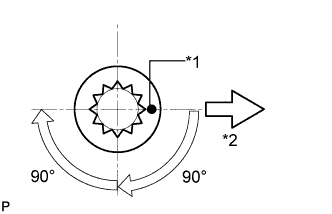
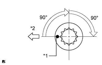
Text in Illustration *1 Painted Mark *2 Engine Front Step 2
-
Mark the cylinder head bolt head with paint as shown in the illustration.
-
Tighten the cylinder head bolts another 90°.
-
-
Step 3
-
Tighten the cylinder head bolts an additional 90°.
-
Check that the painted mark is now facing rearward.
-
-
-
INSTALL NO. 2 CYLINDER HEAD GASKET
-
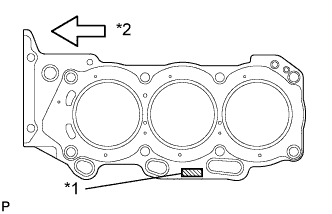
Text in Illustration *1 Lot No. *2 Engine Front Place a new No. 2 cylinder head gasket on the cylinder block surface with the Lot No. stamp upward.
Note
-
Be careful of the installation direction.
-
Gently lower the cylinder head in order not to damage the gasket with the bottom part of the head.
-
-
-
INSTALL CYLINDER HEAD LH
-
Place the cylinder head on the cylinder block.
Note
Be careful not to allow oil to adhere to the bottom part of the cylinder head.
Tech Tips
The cylinder head bolts are tightened in 3 progressive steps.
-
Apply a light coat of engine oil to the threads and under the heads of the cylinder head bolts.
-
Step 1
-
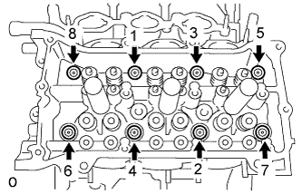
Using a 10 mm bi-hexagon wrench, install and uniformly tighten the 8 cylinder head bolts with the plate washers in several steps in the sequence shown in the illustration.
- Torque:
- 36 N*m { 367 kgf*cm, 26 ft.*lbf }
-
-
Text in Illustration *1 Painted Mark *2 Engine Front Step 2
-
Mark the cylinder head bolt head with paint as shown in the illustration.
-
Tighten the cylinder head bolts another 90°.
-
-
Step 3
-
Tighten the cylinder head bolts an additional 90°.
-
Check that the painted mark is now facing rearward.
-
-
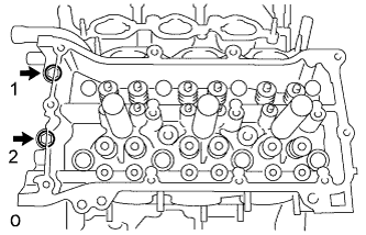
Tighten the 2 bolts in the order shown in the illustration.
- Torque:
- 30 N*m { 306 kgf*cm, 22 ft.*lbf }
-
-
INSTALL OUTLET WATER
-
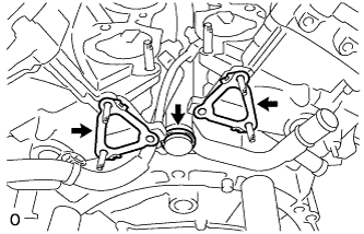
Install 2 new gaskets and a new O-ring.
Tech Tips
Apply soapy water to the O-ring.
-
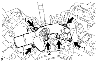
Text in Illustration *1 Nut *2 Bolt Install the outlet water with the 2 bolts and 4 nuts.
- Torque:
- 10 N*m { 102 kgf*cm, 7 ft.*lbf }
Note
Be careful that the O-ring does not get caught between the parts.
-
-
INSTALL VALVE STEM CAP
-
Install the 24 valve stem caps.
-
-
INSTALL VALVE LASH ADJUSTER ASSEMBLY
Note
-
Keep the lash adjuster free of dirt and foreign objects.
-
Only use clean engine oil.
-
Place the lash adjuster into a container filled with engine oil.
-
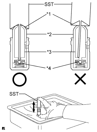
Text in Illustration *1 Tapered Part *2 Plunger *3 Low Pressure Chamber *4 Check Ball Insert the tip of SST into the lash adjuster plunger and use the tip to press down on the check ball inside the plunger.
- SST
- 09276-75010
-
Squeeze SST and lash adjuster together to move the plunger up and down 5 to 6 times.
-
Check the movement of the plunger and bleed the air.
OK Plunger moves up and down. Note
When bleeding air from the high-pressure chamber, make sure that the tip of SST is actually pressing the check ball as shown in the illustration. If the check ball is not pressed, air will not bleed.
-
After bleeding the air, remove SST. Then, try to press the plunger quickly and firmly by hand.
OK Plunger is very difficult to move. If the result is not as specified, replace the valve lash adjuster.
-
Install the valve lash adjusters.
Note
Install each valve lash adjuster to the same place it was removed from.
-
-
INSTALL NO. 1 VALVE ROCKER ARM SUB-ASSEMBLY
-
Apply engine oil to the lash adjuster tip and valve stem cap end.
-
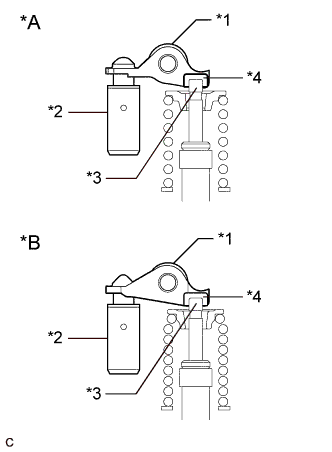
Text in Illustration *A Type A *B Type B *1 No. 1 Valve Rocker Arm Sub-assembly *2 Valve Lash Adjuster Assembly *3 Valve Stem *4 Valve Stem Cap Install the 24 No. 1 valve rocker arm sub-assemblies as shown in the illustration.
-
-
INSTALL NO. 1 CHAIN VIBRATION DAMPER
-
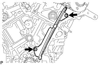
Install the No. 1 chain vibration damper with the 2 bolts.
- Torque:
- 23 N*m { 230 kgf*cm, 17 ft.*lbf }
-
-
INSTALL CAMSHAFT
Tech Tips