CYLINDER HEAD GASKET REMOVAL

-
REMOVE CAMSHAFT
Tech Tips
-
REMOVE NO. 1 CHAIN VIBRATION DAMPER
-
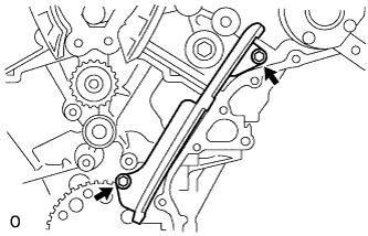
Remove the 2 bolts and No. 1 chain vibration damper.
-
-
REMOVE NO. 1 VALVE ROCKER ARM SUB-ASSEMBLY
-
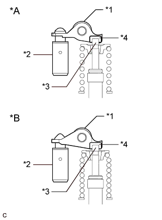
Text in Illustration *A Type A *B Type B *1 No. 1 Valve Rocker Arm Sub-assembly *2 Valve Lash Adjuster Assembly *3 Valve Stem *4 Valve Stem Cap Remove the 24 No. 1 valve rocker arms sub-assemblies.
Tech Tips
Arrange the removed parts in the correct order.
-
-
REMOVE VALVE LASH ADJUSTER ASSEMBLY
-
Remove the 24 valve lash adjuster assemblies from the cylinder head.
Tech Tips
Arrange the removed parts in the correct order.
-
-
REMOVE VALVE STEM CAP
-
Remove the 24 valve stem caps.
Tech Tips
Arrange the removed parts in the correct order.
-
-
REMOVE OUTLET WATER
-
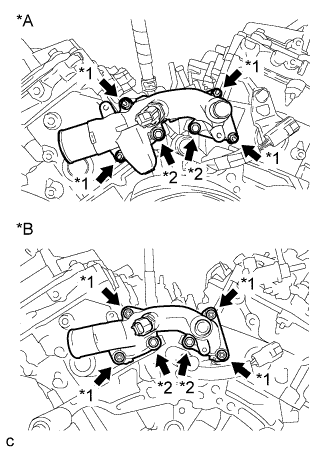
Text in Illustration *A w/ EGR System *B w/o EGR System *1 Nut *2 Bolt Remove the 2 bolts, 4 nuts and outlet water.
-
Remove the 2 gaskets and O-ring.
-
-
REMOVE CYLINDER HEAD SUB-ASSEMBLY
-
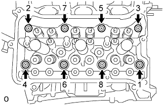
Using a 10 mm bi-hexagon wrench, uniformly loosen the 8 cylinder head bolts in the sequence shown in the illustration. Remove the 8 cylinder head bolts and plate washers.
Note
-
Be careful not to drop washers into the cylinder head sub-assembly.
-
Cylinder head warpage or cracking could result from removing bolts in an incorrect order.
Tech Tips
Arrange the removed parts in the correct order.
-
-
Remove the cylinder head sub-assembly.
-
-
REMOVE CYLINDER HEAD GASKET
-
Remove the cylinder head gasket.
-
-
REMOVE CYLINDER HEAD LH
-
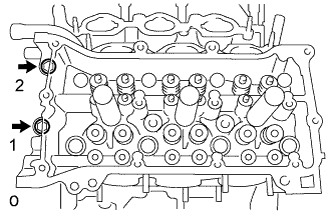
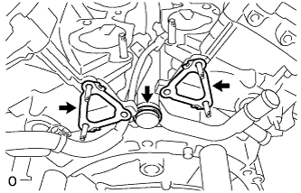
Uniformly loosen and remove the 2 cylinder head set bolts in several steps and in the sequence shown in the illustration.
-
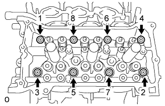
Using a 10 mm bi-hexagon wrench, uniformly loosen the 8 bolts in the sequence shown in the illustration. Remove the 8 cylinder head bolts and plate washers.
Note
-
Be careful not to drop washers into the cylinder head sub-assembly.
-
Cylinder head warpage or cracking could result from removing bolts in an incorrect order.
Tech Tips
Be sure to keep separate the removed parts for each installation position.
-
-
Remove the cylinder head LH.
-
-
REMOVE NO. 2 CYLINDER HEAD GASKET
-
Remove the No. 2 cylinder head gasket.
-
-
INSPECT CYLINDER HEAD SET BOLT
-
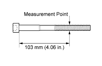
Using a vernier caliper, measure the diameter of the threads at the measurement point shown in the illustration.
Standard diameter 10.85 to 11.00 mm (0.4272 to 0.4330 in.) Minimum diameter 10.70 mm (0.4212 in.) Tech Tips
-
If the diameter is less than the minimum, replace the cylinder head bolt. Failure to do so may lead to engine damage.
-
If there is any thread deformation, replace the cylinder head bolt with a new one.
-
-