CAMSHAFT INSTALLATION

-
INSTALL NO. 3 CAMSHAFT SUB-ASSEMBLY
-
Apply a light coat of engine oil to the No. 3 camshaft journals and camshaft housing sub-assembly LH.
-
Install the No. 3 camshaft to the camshaft housing sub-assembly LH.
-
-
INSTALL NO. 4 CAMSHAFT SUB-ASSEMBLY
-
Apply a light coat of engine oil to the No. 4 camshaft journals and camshaft housing sub-assembly LH.
-
Install the No. 4 camshaft to the camshaft housing sub-assembly LH.
-
-
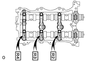
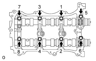
INSTALL CAMSHAFT BEARING CAP (for Bank 2)
-
Apply engine oil to the camshaft bearing caps.
-
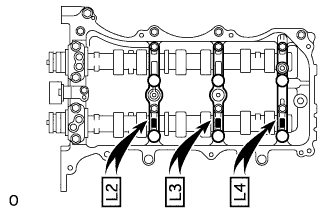
Make sure of the marks and numbers on the camshaft bearing caps and place them in each proper position and direction.
-
Temporarily tighten the 8 bolts in the order shown in the illustration.
- Torque:
- 10 N*m { 102 kgf*cm, 7 ft.*lbf }
-
-
INSTALL CAMSHAFT HOUSING SUB-ASSEMBLY LH
Tech Tips
Type A and Type B can be distinguished by the shape of the compression spring.
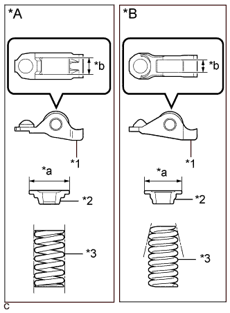
Text in Illustration *A Type A *B Type B *1 No. 1 Valve Rocker Arm Sub-assembly *2 Valve Spring Retainer *3 Inner Compression Spring *a Valve Spring Retainer Diameter *b No. 1 Valve Rocker Arm Sub-assembly Roller Width Type No. 1 Valve Rocker Arm Sub-assembly Roller Width Valve Spring Retainer Diameter Inner Compression Spring Shape A 10.7 mm (0.421 in.) 23.4 mm (0.921 in.) Straight B 8.0 mm (0.315 in.) 18.9 mm (0.744 in.) Taper
-
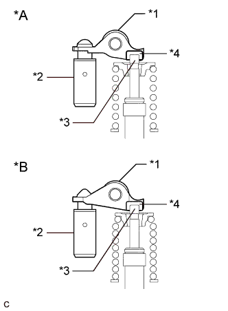
Text in Illustration *A Type A *B Type B *1 No. 1 Valve Rocker Arm Sub-assembly *2 Valve Lash Adjuster Assembly *3 Valve Stem *4 Valve Stem Cap Make sure that the No. 1 valve rocker arm sub-assembly is installed as shown in the illustration.
-
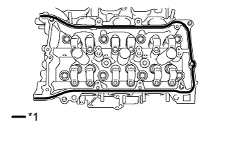
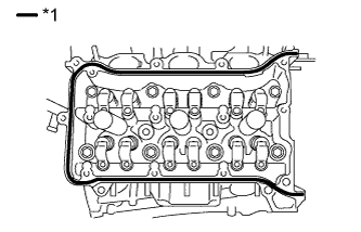
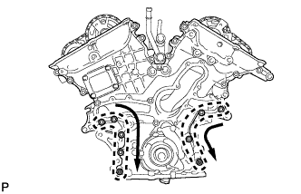
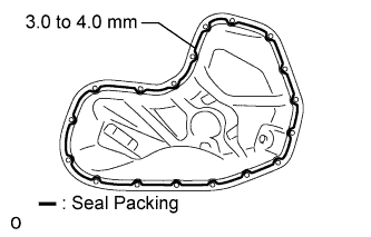
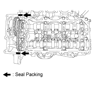
Text in Illustration *1 Seal Packing Apply seal packing in a continuous line as shown in the illustration.
Seal packing Toyota Genuine Seal Packing Black, Three Bond 1207B or equivalent Standard seal diameter 3.5 to 4.5 mm (0.138 to 0.177 in.) Note
-
Remove any oil from the contact surface.
-
Install the camshaft housing sub-assembly LH within 3 minutes.
-
Do not start the engine for at least 2 hours after installing.
-
-
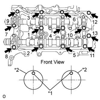
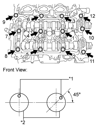
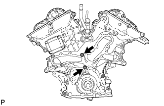
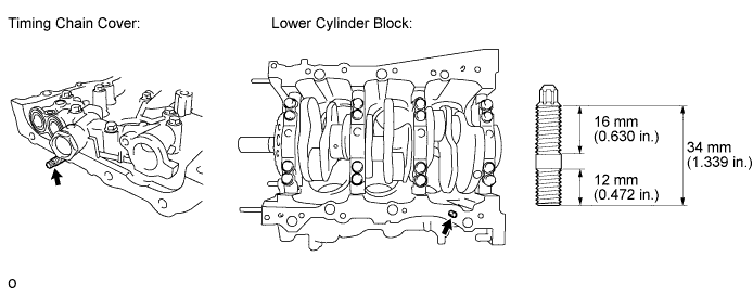
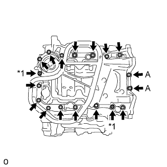
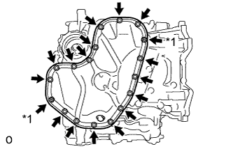
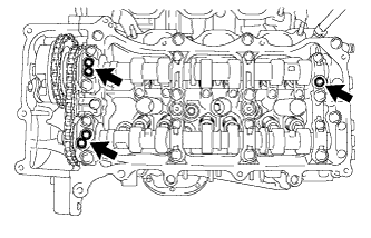
Text in Illustration *1 Knock Pin *2 Camshaft Install the camshaft housing sub-assembly LH and tighten the 13 bolts in the order shown in the illustration.
- Torque:
- 28 N*m { 286 kgf*cm, 21 ft.*lbf }
Note
-
When installing the camshaft housing sub-assembly LH, it is necessary to correctly position the camshafts as shown in the illustration. Failure to correctly position these parts may result in damage due to contact between the pistons and valves. If a camshaft is rotated with a piston at TDC, valve contact will occur.
-
If any of the bolts are loosened during installation, remove the camshaft housing sub-assembly LH, clean the installation surfaces, and reapply seal packing.
-
If the camshaft housing sub-assembly LH is removed because any of the bolts are loosened during installation, make sure that the previously applied seal packing does not enter any oil passages.
-
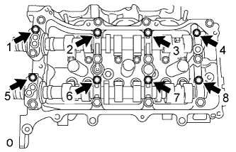
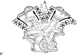
Tighten the 8 bolts in the order shown in the illustration.
- Torque:
- 16 N*m { 163 kgf*cm, 12 ft.*lbf }
-
-
INSTALL CAMSHAFT
-
Apply a light coat of engine oil to the camshaft journals and camshaft housing sub-assembly RH.
-
Install the camshaft to the camshaft housing sub-assembly RH.
-
-
INSTALL NO. 2 CAMSHAFT
-
Apply a light coat of engine oil to the No. 2 camshaft journals and camshaft housing sub-assembly RH.
-
Install the No. 2 camshaft to the camshaft housing sub-assembly RH.
-
-
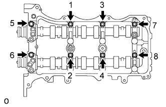
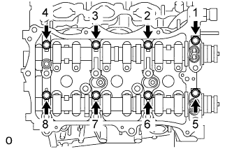
INSTALL CAMSHAFT BEARING CAP (for Bank 1)
-
Apply engine oil to the camshaft bearing caps.
-
Make sure of the marks and numbers on the camshaft bearing caps and place them in each proper position and direction.
-
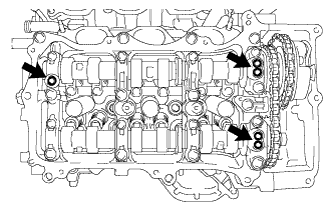
Temporarily tighten the 8 bearing cap bolts in the order shown in the illustration.
- Torque:
- 10 N*m { 102 kgf*cm, 7 ft.*lbf }
-
-
INSTALL CAMSHAFT HOUSING SUB-ASSEMBLY RH
Tech Tips
Type A and Type B can be distinguished by the shape of the compression spring.
Text in Illustration *A Type A *B Type B *1 No. 1 Valve Rocker Arm Sub-assembly *2 Valve Spring Retainer *3 Inner Compression Spring *a Valve Spring Retainer Diameter *b No. 1 Valve Rocker Arm Sub-assembly Roller Width Type No. 1 Valve Rocker Arm Sub-assembly Roller Width Valve Spring Retainer Diameter Inner Compression Spring Shape A 10.7 mm (0.421 in.) 23.4 mm (0.921 in.) Straight B 8.0 mm (0.315 in.) 18.9 mm (0.744 in.) Taper
-
Text in Illustration *A Type A *B Type B *1 No. 1 Valve Rocker Arm Sub-assembly *2 Valve Lash Adjuster Assembly *3 Valve Stem *4 Valve Stem Cap Make sure that the No. 1 valve rocker arm sub-assembly is installed as shown in the illustration.
-
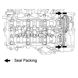
Text in Illustration *1 Seal Packing Apply seal packing in a continuous line as shown in the illustration.
Seal packing Toyota Genuine Seal Packing Black, Three Bond 1207B or equivalent Standard seal diameter 3.5 to 4.0 mm (0.138 to 0.157 in.) Note
-
Remove any oil from the contact surface.
-
Install the camshaft housing sub-assembly RH within 3 minutes.
-
Do not start the engine for at least 2 hours after installing.
-
-
Text in Illustration *1 Knock Pin *2 Camshaft Install the camshaft housing sub-assembly RH and tighten the 12 bolts in the order shown in the illustration.
- Torque:
- 28 N*m { 286 kgf*cm, 21 ft.*lbf }
Note
-
When installing the camshaft housing RH, it is necessary to correctly position the camshafts as shown in the illustration.
Failure to correctly position these parts may result in damage due to contact between the pistons and valves. If a camshaft is rotated with a piston at TDC, valve contact will occur.
-
If any of the bolts is loosened during installation, remove the camshaft housing sub-assembly RH, clean the installation surfaces, and reapply seal packing.
-
If the camshaft housing sub-assembly RH is removed because any of the bolts is loosened during installation, make sure that the previously applied seal packing does not enter any oil passages.
-
Tighten the 8 bolts in the order shown in the illustration.
- Torque:
- 16 N*m { 163 kgf*cm, 12 ft.*lbf }
-
-
INSTALL NO. 3 CHAIN TENSIONER ASSEMBLY
-
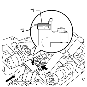
Text in Illustration *1 Plunger *2 Pin Install the No. 3 chain tensioner assembly with the bolt.
- Torque:
- 21 N*m { 214 kgf*cm, 15 ft.*lbf }
-
While pushing in the tensioner, insert a pin of 1.0 mm (0.0394 in.) diameter into the hole to hold it.
-
-
INSTALL CAMSHAFT TIMING GEARS AND NO. 2 CHAIN (for Bank 2)
-
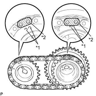
Text in Illustration *1 Timing Mark *2 Mark Plate Align the mark plates (yellow) with the timing marks of the camshaft timing gear assemblies as shown in the illustration.
-
Apply a light coat of engine oil to the bolt threads and bolt-seating surface.
-
Align the knock pin of the camshaft with the pin hole of the camshaft timing gear assembly. Install the camshaft timing gear assembly and camshaft timing sprocket LH with the No. 2 chain sub-assembly installed.
-
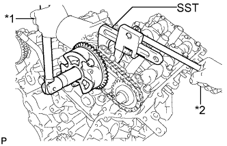
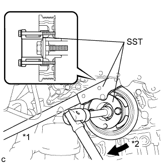
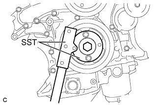
Text in Illustration *1 Turn *2 Hold Using SST to hold the hexagonal portion of each camshaft, tighten the bolts of the camshaft timing gear assembly and the camshaft timing sprocket.
- SST
- 09922-10010
- Torque:
- 100 N*m { 1020 kgf*cm, 74 ft.*lbf }
-
Remove the pin from the No. 3 chain tensioner assembly.
-
-
INSTALL NO. 2 CHAIN TENSIONER ASSEMBLY
-
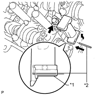
Text in Illustration *1 Plunger *2 Pin Install the No. 2 chain tensioner assembly with the bolt.
- Torque:
- 21 N*m { 214 kgf*cm, 15 ft.*lbf }
-
While pushing in the No. 2 chain tensioner assembly, insert a pin of 1.0 mm (0.0394 in.) diameter into the hole to hold it.
-
-
INSTALL CAMSHAFT TIMING GEARS AND NO. 2 CHAIN (for Bank 1)
-
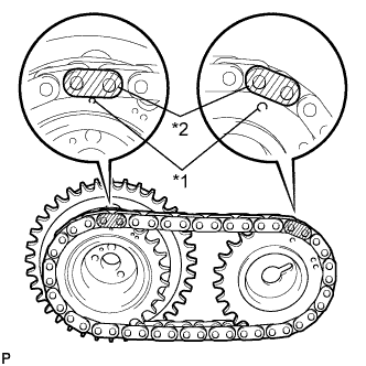
Text in Illustration *1 Timing Mark *2 Mark Plate Align the mark plates (yellow) with the timing marks of the camshaft timing gear assemblies as shown in the illustration.
-
Apply a light coat of engine oil to the bolt threads and bolt-seating surface.
-
Align the knock pin of the camshaft with the pin hole of the camshaft timing gear assembly. Install the camshaft timing gear assembly and camshaft timing sprocket with the No. 2 chain sub-assembly installed.
-
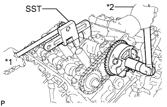
Text in Illustration *1 Turn *2 Hold Using SST to hold the hexagonal portion of each camshaft, tighten the bolts of the camshaft timing gear assembly and the camshaft timing sprocket.
- SST
- 09922-10010
- Torque:
- 100 N*m { 1020 kgf*cm, 74 ft.*lbf }
-
Remove the pin from the No. 2 chain tensioner assembly.
-
-
INSTALL IDLE SPROCKET ASSEMBLY
-
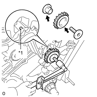
Text in Illustration *1 Knock Pin Apply a light coat of engine oil to the rotating surface of the No. 1 idle gear shaft.
-
Temporarily install the No. 1 idle gear shaft and idle sprocket with the No. 2 idle gear shaft while aligning the knock pin of the No. 1 idle gear shaft with the knock pin groove of the cylinder block.
Note
Be careful of the idle gear installation position.
Tech Tips
Check that no foreign objects are on the No. 1 and No. 2 idle gear shafts.
-
Using a 10 mm hexagon wrench, tighten the No. 2 idle gear shaft.
- Torque:
- 60 N*m { 612 kgf*cm, 44 ft.*lbf }
Tech Tips
After installing the idle sprocket assembly, check that the idle sprocket turns smoothly.
-
-
INSTALL CHAIN SUB-ASSEMBLY
-
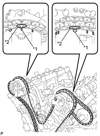
Text in Illustration *1 Timing Mark *2 Mark Plate Align the mark plates and timing marks as shown in the illustration and install the chain.
Tech Tips
The camshaft mark plates are orange.
-
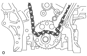
Do not pass the chain over the crankshaft, just temporarily place it on the crankshaft.
-
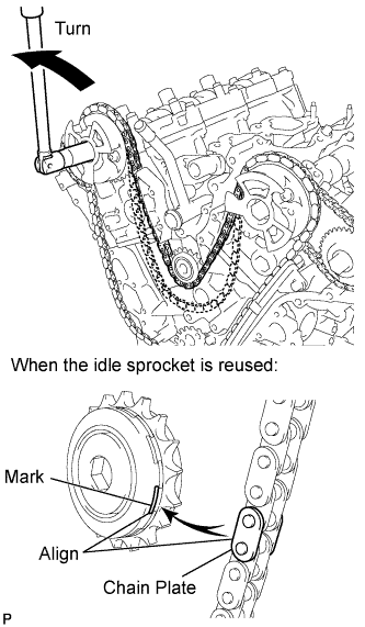
Turn the camshaft timing gear assembly on bank 1 counterclockwise to tighten the chain between the banks.
Note
When the idle sprocket assembly is reused, align the chain plate with the mark where the plate had been in order to tighten the chain between the banks.
-
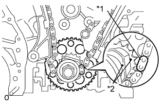
Text in Illustration *1 Mark Plate *2 Timing Plate Align the mark plate and timing marks as shown in the illustration and install the chain onto the crankshaft timing sprocket.
Tech Tips
The crankshaft mark plate is yellow.
-
Temporarily tighten the pulley set bolt.
-
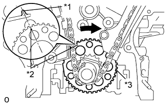
Text in Illustration *1 Center Line *2 Timing Mark *3 Sensor Plate Turn the crankshaft clockwise to set it to the RH block bore center line (TDC/compression).
-
-
INSTALL CHAIN TENSIONER SLIPPER
-
Install the chain tensioner slipper.
-
-
INSTALL NO. 1 CHAIN TENSIONER ASSEMBLY
-
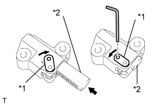
Text in Illustration *1 Stopper Plate *2 Plunger Move the stopper plate upward to release the lock, and push the plunger deep into the tensioner.
-
Move the stopper plate downward to set the lock, and insert a hexagon wrench into the hole of the stopper plate.
-
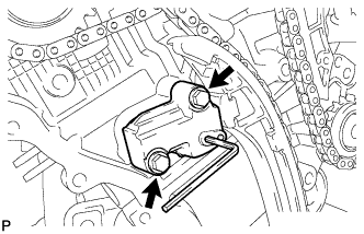
Install the No. 1 chain tensioner assembly with the 2 bolts.
- Torque:
- 10 N*m { 102 kgf*cm, 7 ft.*lbf }
-
Remove the hexagon wrench from the No. 1 chain tensioner assembly.
-
-
INSPECT VALVE TIMING
-
Check the camshaft timing marks.
Note
-
Check each timing mark from a viewpoint directly inline with the center of the camshaft and the timing mark on each camshaft timing gear.
-
If the timing marks are checked from any other viewpoint, the valve timing may appear misaligned.
-
-
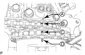
Check that each camshaft timing mark is positioned as shown in the illustration.
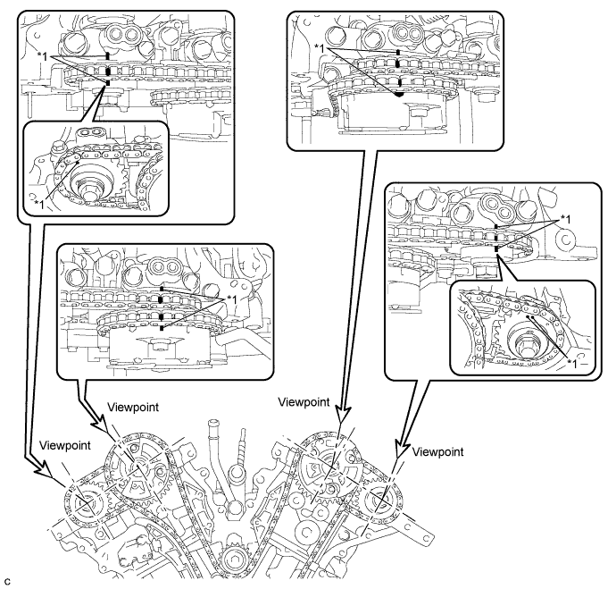
Text in Illustration *1 Timing Mark - - Tech Tips
For the intake camshaft:
Be sure to check mark A at the point when marks B, C, and D are positioned in line. If the marks are checked from any other viewpoint, they cannot be checked correctly.
-
If the valve timing is misaligned, reinstall the timing chain.
-
Remove the pulley set bolt.
-
-
INSTALL TIMING CHAIN CASE OIL SEAL
-
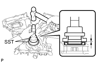
Using SST, tap in a new timing chain case oil seal until its surface is flush with the timing gear case edge.
- SST
- 09223-22010
- 09506-35010
Oil seal tap in depth -1.0 to 1.0 mm (-0.0393 to 0.0393) Note
-
Keep the lip free of foreign matter.
-
Do not tap on the oil seal at an angle.
-
Make sure that the oil seal edge does not stick out of the timing chain case.
-
-
INSTALL TIMING CHAIN COVER SUB-ASSEMBLY
-
Remove any old packing material remaining on the sealing surfaces before applying seal packing.
-
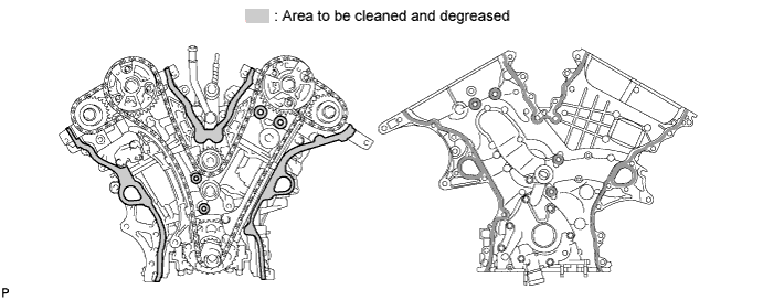
Clean and degrease the contact surfaces of the timing chain cover, cylinder head and cylinder block, and confirm that no oil, moisture, or other foreign matter remains on the surfaces.
-
Install a new gasket.
-
Apply seal packing in a continuous line to the engine unit as shown in the following illustration.
Seal packing Toyota Genuine Seal Packing Black, Three Bond 1207B or equivalent Seal diameter 3.0 mm (0.118 in.) Note
-
When the contact surfaces are wet, wipe them with an oil-free cloth before applying seal packing.
-
Install the chain cover within 3 minutes and tighten the bolts within 10 minutes after applying seal packing.
-
Do not add engine oil for at least 2 hours after installing the chain cover.
-
Do not start the engine for at least 2 hours after installing the chain cover.
-
-
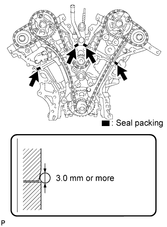
Apply seal packing in a continuous line to the timing chain cover as shown in the following illustration.
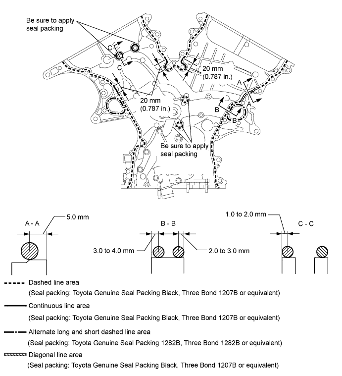
Seal packing Toyota Genuine Seal Packing Black, Three Bond 1207B or equivalent Toyota Genuine Seal Packing 1282B, Three Bond 1282B or equivalent Note
-
If the contact surfaces are wet, wipe them with an oil-free cloth before applying seal packing.
-
Install the chain cover within 3 minutes and tighten the bolts within 10 minutes after applying seal packing.
-
Do not start the engine for at least 2 hours after installing.
Seal Packing Application Chart Area Seal Packing Diameter Application Position from Inside Seal Line Continuous Line Area 4.5 mm or more (0.177 in. or more) 3.0 to 4.0 mm (0.118 to 0.158 in.) Alternate Long and Short Dashed Line Area 3.5 mm or more (0.138 in. or more) 2.0 to 3.0 mm (0.0787 to 0.118 in.) Dashed Line Area 3.5 mm or more (0.138 in. or more) 3.0 to 4.0 mm (0.118 to 0.158 in.) Diagonal Line Area 6.0 mm or more (0.236 in. or more) 5.0 mm (0.197 in.) -
-
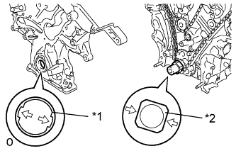
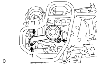
Text in Illustration *1 Drive Rotor Spline *2 Crankshaft Align the oil pump's drive rotor spline and the crankshaft as shown in the illustration. Install the spline and chain cover to the crankshaft.
-
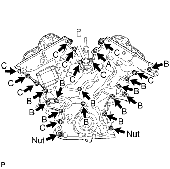
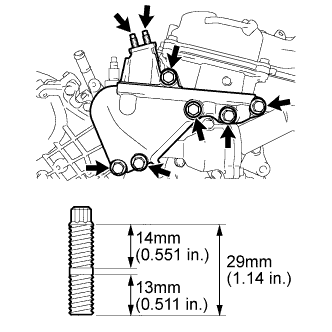
Temporarily tighten the timing chain cover with the 23 bolts and 2 nuts.
Bolt Length Item Length Bolt A 40 mm (1.57 in.) Bolt B 55 mm (2.17 in.) Bolt C 25 mm (0.984 in.) Note
Make sure that there is no oil on the bolt and nut threads.
-
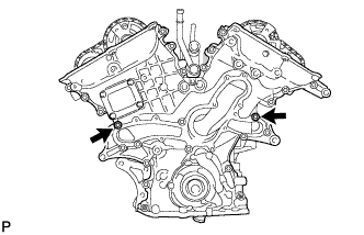
Fully tighten the 2 bolts.
- Torque:
- 21 N*m { 214 kgf*cm, 15 ft.*lbf }
-
Fully tighten the 2 bolts.
- Torque:
- 21 N*m { 214 kgf*cm, 15 ft.*lbf }
-
Fully tighten the 7 bolts and 2 nuts.
- Torque:
- 21 N*m { 214 kgf*cm, 15 ft.*lbf }
Tech Tips
First tighten the upper bolts and nuts followed by lower bolts and nuts as shown in the illustration.
-
Fully tighten the 12 bolts.
- Torque:
- Bolt A
- 43 N*m { 438 kgf*cm, 32 ft.*lbf }
- Torque:
- Except bolt A
- 21 N*m { 214 kgf*cm, 15 ft.*lbf }
Tech Tips
Tighten the bolts in the order of lower to upper as shown in the illustration.
-
Install a new chain cover plate gasket and the chain cover plate with the 4 bolts.
- Torque:
- 9.1 N*m { 93 kgf*cm, 81 in.*lbf }
-
-
INSTALL INLET WATER HOUSING
-
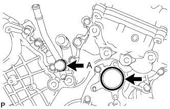
Install 2 new O-rings.
Tech Tips
Apply a small amount of water or soapy water to O-ring (A) shown in the illustration before installation.
-
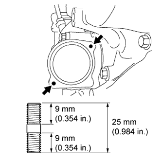
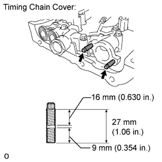
Install the 2 stud bolts.
- Torque:
- 4.0 N*m { 41 kgf*cm, 35 in.*lbf }
-
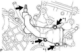
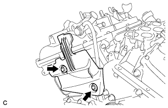
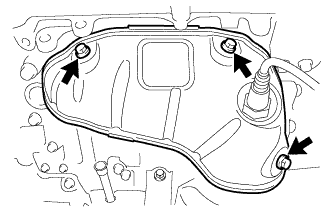
Text in Illustration *1 Bolt *2 Nut Install the inlet water housing with the 2 bolts and nut.
- Torque:
- 10 N*m { 102 kgf*cm, 7 ft.*lbf }
Note
Be careful that the O-ring does not get caught between the parts.
-
Connect the No. 1 water by-pass hose.
-
Apply adhesive around the drain cock.
Adhesive Toyota Genuine Adhesive 1324, Three Bond 1324 or equivalent -
Install the drain cock assembly to the inlet water housing.
- Torque:
- 30 N*m { 306 kgf*cm, 22 ft.*lbf }
-
Install the drain cock plug to the drain cock assembly.
- Torque:
- 13 N*m { 130 kgf*cm, 9 ft.*lbf }
-
Install a new gasket to the thermostat.
-
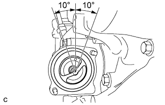
Align the thermostat jiggle valve with the upper stud bolt, and insert the thermostat in the inlet water housing.
Tech Tips
The jiggle valve may be set within 10° of either side of the prescribed position.
-
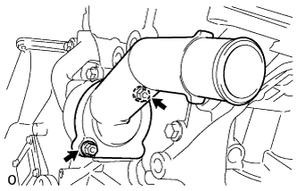
Install the inlet water with the 2 nuts.
- Torque:
- 10 N*m { 102 kgf*cm, 7 ft.*lbf }
-
-
INSTALL FRONT NO. 1 ENGINE MOUNTING BRACKET LH
-
Install the front No. 1 engine mounting bracket LH with the 6 bolts.
- Torque:
- 54 N*m { 550 kgf*cm, 40 ft.*lbf }
Note
-
Install the inlet water and mounting bracket within 15 minutes after installing the chain cover.
-
Do not start the engine for at least 2 hours after installation.
-
Using an E8 "TORX" socket wrench, install the 2 stud bolts.
- Torque:
- 10 N*m { 102 kgf*cm, 7 ft.*lbf }
-
-
INSTALL OIL PAN SUB-ASSEMBLY
-
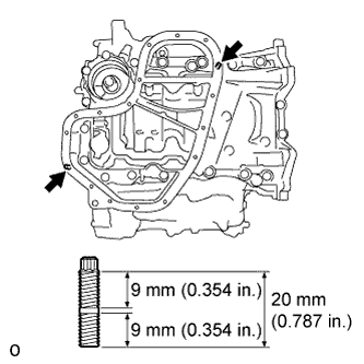
Using an E8 "TORX" socket wrench, install the 2 stud bolts.
- Torque:
- 10 N*m { 102 kgf*cm, 7 ft.*lbf }
-
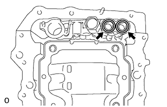
Install 2 new O-rings.
-
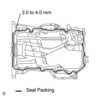
Apply seal packing in a continuous line as shown in the illustration.
Seal packing Toyota Genuine Seal Packing Black, Three Bond 1207B or equivalent Seal diameter 3.0 to 4.0 mm (0.118 to 0.157 in.) Note
-
Remove any oil from the contact surfaces.
-
Install the oil pan within 3 minutes after applying seal packing.
-
Do not start the engine for at least 2 hours after installing.
-
-
Text in Illustration *1 Nut Install the oil pan with the 16 bolts and 2 nuts.
- Torque:
- Bolts A
- 10 N*m { 102 kgf*cm, 7 ft.*lbf }
- Except bolts A
- 21 N*m { 214 kgf*cm, 15 ft.*lbf }
-
-
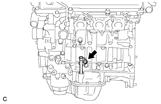
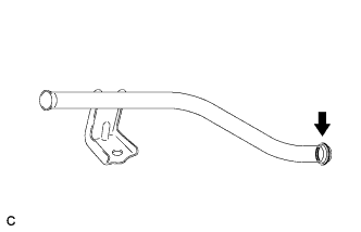
INSTALL OIL STRAINER SUB-ASSEMBLY
-
Using an E6 "TORX" socket, install the 2 stud bolts as shown in the illustration.
- Torque:
- 4.0 N*m { 41 kgf*cm, 35 in.*lbf }
-
Text in Illustration *1 Nut Install a new gasket and the oil strainer sub-assembly with the bolt and 2 nuts.
- Torque:
- 10 N*m { 102 kgf*cm, 7 ft.*lbf }
-
-
INSTALL NO. 2 OIL PAN SUB-ASSEMBLY
-
Using an E6 "TORX" socket, install the 2 stud bolts as shown in the illustration.
- Torque:
- 4.0 N*m { 41 kgf*cm, 35 in.*lbf }
-
Apply seal packing in a continuous line as shown in the illustration.
Seal packing Toyota Genuine Seal Packing Black, Three Bond 1207B or equivalent Seal diameter 3.0 to 4.0 mm (0.118 to 0.157 in.) Note
-
Remove any oil from the contact surfaces.
-
Install the No. 2 oil pan sub-assembly within 3 minutes after applying seal packing.
-
Do not start the engine for at least 2 hours after installing.
-
-
Text in Illustration *1 Nut Install the No. 2 oil pan sub-assembly with the 16 bolts and 2 nuts.
- Torque:
- 10 N*m { 102 kgf*cm, 7 ft.*lbf }
-
-
INSTALL CYLINDER HEAD COVER SUB-ASSEMBLY
-
Install 3 new gaskets as shown in the illustration.
-
Install a new cylinder head cover gasket to the cylinder head cover sub-assembly.
-
Apply seal packing as shown in the illustration.
Seal packing Toyota Genuine Seal Packing Black, Three Bond 1207B or equivalent Note
-
Remove any oil from the contact surfaces.
-
Install the head cover within 3 minutes after applying seal packing.
-
Do not start the engine for at least 2 hours after installing.
-
-
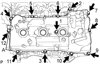
Install the head cover with the 12 bolts and a new seal washer.
- Torque:
- Bolts A
- 21 N*m { 214 kgf*cm, 15 ft.*lbf }
- Except bolts A
- 10 N*m { 102 kgf*cm, 7 ft.*lbf }
Tech Tips
After tightening all bolts, check the tightening torque of 1 and 11. Retighten the bolt if necessary.
-
-
INSTALL CYLINDER HEAD COVER SUB-ASSEMBLY LH
-
Install 3 new gaskets as shown in the illustration.
-
Install a new cylinder head cover gasket to the cylinder head cover sub-assembly LH.
-
Apply seal packing as shown in the illustration.
Seal packing Toyota Genuine Seal Packing Black, Three Bond 1207B or equivalent Note
-
Remove any oil from the contact surfaces.
-
Install the cylinder head cover sub-assembly LH within 3 minutes after applying seal packing.
-
Do not start the engine for at least 2 hours after installing.
-
-
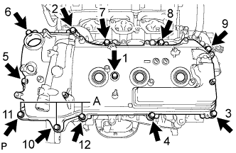
Install the cylinder head cover sub-assembly LH with the 12 bolts and a new seal washer.
- Torque:
- Bolts A
- 21 N*m { 214 kgf*cm, 15 ft.*lbf }
- Except bolts A
- 10 N*m { 102 kgf*cm, 7 ft.*lbf }
Tech Tips
After tightening all bolts, check the tightening torque of 1 and 10. Retighten the bolt if necessary.
-
-
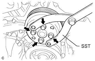
INSTALL CRANKSHAFT PULLEY
-
Text in Illustration *1 Hold *2 Turn Using SST, install the pulley bolt.
- SST
- 09213-70011 ( 09213-70020 )
- 09330-00021
- Torque:
- 250 N*m { 2550 kgf*cm, 184 ft.*lbf }
-
-
INSTALL NO. 1 OIL PIPE
-
Make sure that there is no foreign matter on the mesh of the oil control valve filter LH.
Note
Do not touch the mesh when installing the oil control valve filter.
-
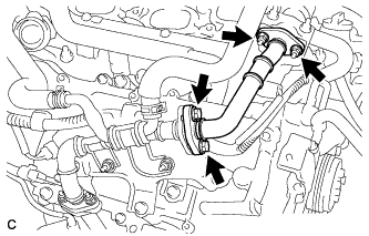
Text in Illustration *1 Oil Pipe Union Install the oil control valve filter LH to the oil pipe union. Install new gaskets and temporarily install the oil pipe (on the head cover side) with the union.
-
Install a new gasket and temporarily install the oil pipe (on the cylinder head side) with the union.
-
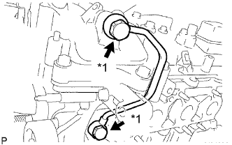
Tighten the oil pipe union (on the head cover side).
- Torque:
- 65 N*m { 663 kgf*cm, 48 ft.*lbf }
-
Tighten the oil pipe union (on the cylinder head side).
- Torque:
- 65 N*m { 663 kgf*cm, 48 ft.*lbf }
Note
If the link that connects the gaskets is broken, remove the connecting link by using side cutters or a similar tool.
-
-
INSTALL OIL PIPE
-
Make sure that there is no foreign matter on the mesh of the oil control valve filter RH.
Note
Do not touch the mesh when installing the oil control valve filter.
-
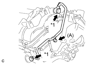
Text in Illustration *1 Oil Pipe Union Install the oil control valve filter RH to the oil pipe union. Install new gaskets and temporarily install the oil pipe (on the head cover side) with the union.
-
Install a new gasket and temporarily install the oil pipe (on the cylinder head side) with the union.
-
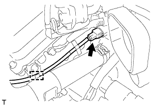
Install the bolt (A) to the cylinder head.
- Torque:
- 10 N*m { 102 kgf*cm, 7 ft.*lbf }
-
Tighten the oil pipe union (on the head cover side).
- Torque:
- 65 N*m { 663 kgf*cm, 48 ft.*lbf }
-
Tighten the oil pipe union (on the cylinder head side).
- Torque:
- 65 N*m { 663 kgf*cm, 48 ft.*lbf }
Note
If the link that connects the gaskets is broken, remove the connecting link by using side cutters or a similar tool.
-
-
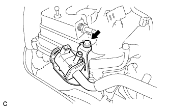
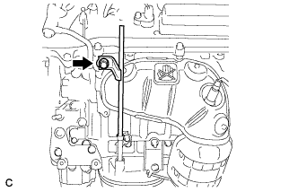
INSTALL CRANK POSITION SENSOR
-
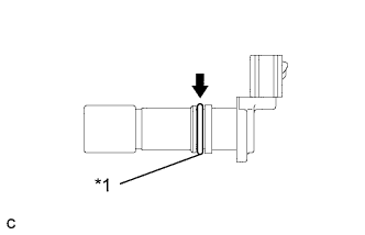
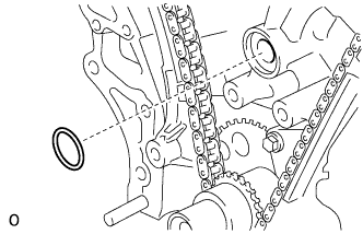
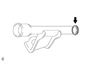
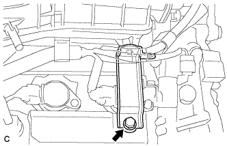
Text in Illustration *1 O-ring Apply a light coat of engine oil to the O-ring on the crank position sensor.
-
Install the crank position sensor with the bolt.
- Torque:
- 10 N*m { 102 kgf*cm, 7 ft.*lbf }
-
Connect the crank position sensor connector.
-
-
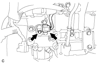
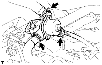
INSTALL NO. 1 VACUUM SWITCHING VALVE
-
Install the No. 1 vacuum switching valve with the bolt.
- Torque:
- 10 N*m { 102 kgf*cm, 7 ft.*lbf }
-
-
INSTALL RADIO SETTING CONDENSER
-
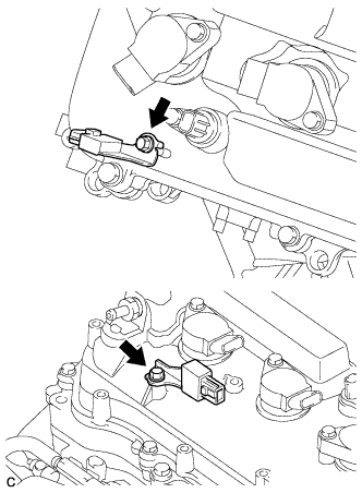
Install the 2 radio setting condensers with the 2 bolts.
- Torque:
- 10 N*m { 102 kgf*cm, 7 ft.*lbf }
-
-
INSTALL WATER PUMP PULLEY
-
Temporarily install the water pump pulley with the 4 bolts.
-
Using SST, hold the water pump pulley.
- SST
- 09960-10010 ( 09962-01000, 09963-00700 )
-
Tighten the 4 bolts.
- Torque:
- 21 N*m { 214 kgf*cm, 15 ft.*lbf }
-
-
INSTALL NO. 2 TIMING GEAR COVER
-
Install the No. 2 timing gear cover with the 2 bolts.
- Torque:
- 6.0 N*m { 61 kgf*cm, 53 in.*lbf }
-
-
INSTALL V-RIBBED BELT TENSIONER ASSEMBLY
-
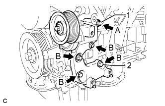
Temporarily install the V-ribbed belt tensioner assembly with the 5 bolts.
Tech Tips
Each bolt length is as follows:
A: 70 mm (2.76 in.)
B: 33 mm (1.30 in.)
-
Install the V-ribbed belt tensioner assembly by tightening the bolt 1 and bolt 2 in the order shown in the illustration.
- Torque:
- 43 N*m { 438 kgf*cm, 32 ft.*lbf }
-
Tighten the other bolts.
- Torque:
- 43 N*m { 438 kgf*cm, 32 ft.*lbf }
-
-
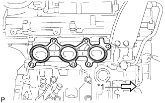
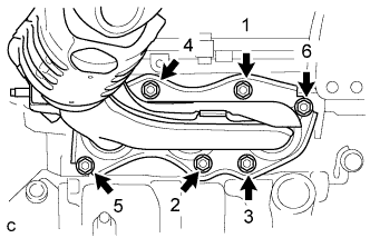
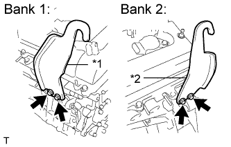
INSTALL EXHAUST MANIFOLD SUB-ASSEMBLY LH
-
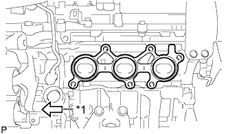
Text in Illustration *1 Front Install a new gasket as shown in the illustration.
-
Install the exhaust manifold sub-assembly LH with the 6 nuts in the order shown in the illustration.
- Torque:
- 21 N*m { 214 kgf*cm, 15 ft.*lbf }
-
-
INSTALL NO. 2 EXHAUST MANIFOLD HEAT INSULATOR
-
Install the No. 2 exhaust manifold heat insulator with the 3 bolts.
- Torque:
- 8.5 N*m { 87 kgf*cm, 75 in.*lbf }
-
Connect the sensor wire to the radiator pipe clamp.
-
Connect the air fuel ratio sensor connector (for Bank 2 Sensor 1).
-
-
INSTALL NO. 2 MANIFOLD STAY
-
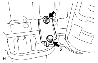
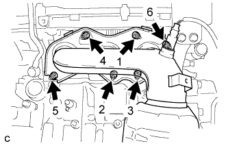
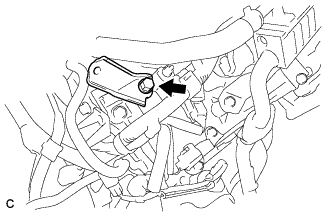
Install the No. 2 manifold stay by tightening the bolt and nut in the order shown in the illustration.
- Torque:
- 34 N*m { 347 kgf*cm, 25 ft.*lbf }
-
-
INSTALL ENGINE OIL LEVEL DIPSTICK GUIDE
-
Apply a light coat of engine oil to a new O-ring and install it to the engine oil level dipstick guide.
-
Install the engine oil level dipstick guide with the bolt.
- Torque:
- 21 N*m { 214 kgf*cm, 15 ft.*lbf }
-
-
INSTALL NO. 2 ENGINE OIL LEVEL DIPSTICK GUIDE
-
Install a new O-ring to the No. 2 engine oil level dipstick guide.
-
Apply a light coat of engine oil to the O-ring.
-
Push in the No. 2 engine oil level dipstick guide end into the No. 1 engine oil level dipstick guide.
-
Install the No. 2 engine oil level dipstick guide with the bolt.
- Torque:
- 21 N*m { 214 kgf*cm, 15 ft.*lbf }
-
Install the engine oil level dipstick.
-
-
INSTALL EXHAUST MANIFOLD SUB-ASSEMBLY RH
-
Text in Illustration *1 Front Install a new gasket as shown in the illustration.
-
Install the exhaust manifold sub-assembly RH with the 6 nuts in the order shown in the illustration.
- Torque:
- 21 N*m { 214 kgf*cm, 15 ft.*lbf }
-
-
INSTALL INTAKE MANIFOLD
Note
DO NOT apply oil to the bolts listed below:
Tightening Part Intake Manifold and Cylinder Head Sub-assembly RH Intake Manifold and Cylinder Head Sub-assembly LH
-
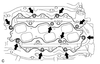
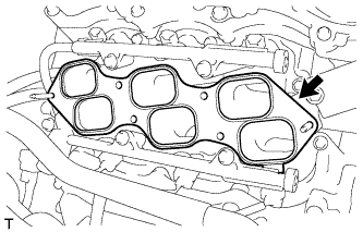
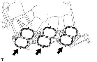
Set a new gasket on each cylinder head.
Note
-
Align the port holes of the gasket and cylinder head.
-
Make sure that the gasket is installed in the correct direction.
-
-
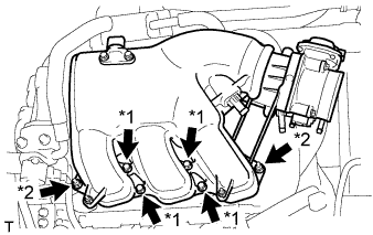
Set the intake manifold on the cylinder heads.
-
Install and tighten the 6 bolts and 4 nuts uniformly in several steps.
- Torque:
- 21 N*m { 214 kgf*cm, 15 ft.*lbf }
-
-
INSTALL NO. 2 ENGINE MOUNTING STAY RH
-
Install the No. 2 engine mounting stay RH with the bolt.
- Torque:
- 21 N*m { 214 kgf*cm, 15 ft.*lbf }
-
-
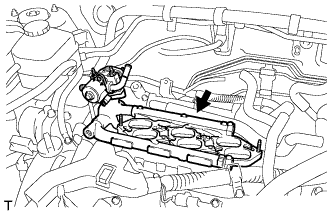
INSTALL IGNITION COIL ASSEMBLY
-
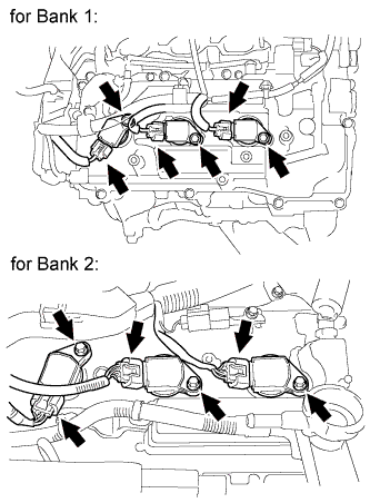
Install the 6 ignition coils with the 6 bolts.
- Torque:
- 10 N*m { 102 kgf*cm, 7 ft.*lbf }
-
Connect the 6 ignition coil connectors.
-
-
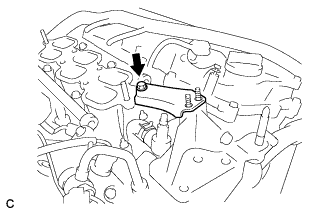
INSTALL NO. 1 SURGE TANK STAY
-
Install the No. 1 surge tank stay with the bolt.
- Torque:
- 21 N*m { 214 kgf*cm, 15 ft.*lbf }
-
-
INSTALL EGR DELIVERY CHAMBER
-
Set a new No. 2 intake manifold gasket.
-
Install the EGR delivery chamber.
-
Connect the 2 water hoses and connector.
-
-
INSTALL NO. 1 EGR COOLER BRACKET
-
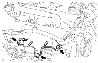
Install the No. 1 EGR cooler bracket with the 3 bolts.
- Torque:
- 21 N*m { 214 kgf*cm, 15 ft.*lbf }
-
-
INSTALL EGR COOLER ASSEMBLY
-
Type A:
-
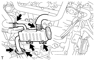
Install a new gasket and the EGR cooler assembly with the 4 nuts.
- Torque:
- 21 N*m { 214 kgf*cm, 15 ft.*lbf }
-
Connect the 2 water hoses.
-
-
Type B:
-
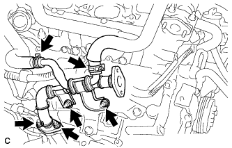
Install a new gasket and the EGR cooler assembly with the 4 nuts.
- Torque:
- 21 N*m { 214 kgf*cm, 15 ft.*lbf }
-
Connect the 2 water hoses.
-
-
-
INSTALL NO. 2 EGR PIPE
-
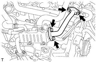
Install 2 new gaskets and the No. 2 EGR pipe with the 2 nuts and 2 bolts. (Type A)
- Torque:
- 21 N*m { 214 kgf*cm, 15 ft.*lbf }
-
Install 2 new gaskets and the No. 2 EGR pipe with the 2 nuts and 2 bolts. (Type B)
- Torque:
- 21 N*m { 214 kgf*cm, 15 ft.*lbf }
-
-
INSTALL THROTTLE BODY BRACKET
-
Install the throttle body bracket with the bolt.
- Torque:
- 21 N*m { 214 kgf*cm, 15 ft.*lbf }
-
-
INSTALL INTAKE AIR SURGE TANK ASSEMBLY
NOTICE DO NOT apply oil to the bolts listed below: Tightening Part Surge Tank and Intake Manifold No. 1 Surge Tank Stay and Surge Tank Throttle Body Bracket and Surge Tank
-
Install 3 new air surge tank to intake manifold gaskets to the intake air surge tank.
-
Text in Illustration *1 Bolt *2 Nut Using a 5 mm hexagon socket wrench, install the intake air surge tank assembly with the 4 bolts and 2 nuts.
- Torque:
- Bolt
- 18 N*m { 184 kgf*cm, 13 ft.*lbf }
- Nut
- 16 N*m { 163 kgf*cm, 12 ft.*lbf }
-

Install the throttle body bracket and No. 1 surge tank stay with the 2 bolts.
- Torque:
- 21 N*m { 214 kgf*cm, 15 ft.*lbf }
-
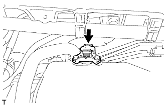
Connect the connector to the manifold absolute pressure sensor.
-
Connect the ventilation hose.
-
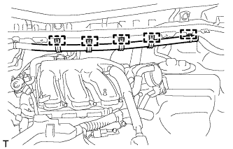
Install the 5 clamps and connect the main wire to the body.
-
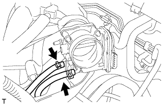
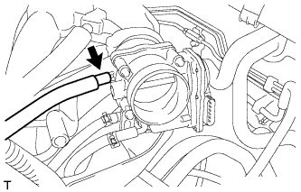
Connect the 2 water by-pass hoses to the throttle body assembly.
-
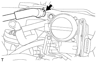
Connect the fuel vapor feed hose.
-
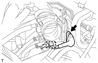
Connect the throttle body assembly connector and wire harness clamp to the throttle body assembly.
-
-
INSTALL ENGINE HANGERS
-
Text in Illustration *1 No. 1 Engine Hanger *2 No. 2 Engine Hanger Install the 2 engine hangers with the 4 bolts as shown in the illustration.
- Torque:
- 33 N*m { 337 kgf*cm, 24 ft.*lbf }
Part No. Item Part No. No. 1 Engine Hanger 12281-31120 No. 2 Engine Hanger 12282-31100 Bolt 91671-10825 -
Attach the engine sling device and hang the engine with the chain block.
-
-
REMOVE ENGINE STAND
-
Remove the engine assembly from the engine stand.
-
-
INSTALL FLYWHEEL SUB-ASSEMBLY
-
Using SST, hold the crankshaft pulley.
- SST
- 09213-70011 ( 09213-70020 )
- 09330-00021
-
Clean the 8 bolts and 8 bolt holes.
-
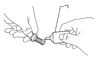
Text in Illustration *1 Adhesive Apply adhesive to 2 or 3 threads of the 8 bolts.
Adhesive Toyota Genuine Adhesive 1324, Three Bond 1324 or equivalent -
Install the flywheel sub-assembly.
-
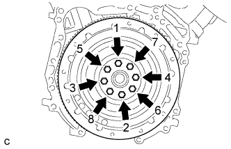
In several steps, uniformly install and tighten the 8 bolts in the sequence shown in the illustration.
- Torque:
- 83 N*m { 846 kgf*cm, 61 ft.*lbf }
Note
Do not start the engine within 1 hour after installing.
-
-
INSTALL TRANSMISSION INPUT DAMPER ASSEMBLY
-
Using SST, hold the crankshaft pulley.
- SST
- 09213-70011 ( 09213-70020 )
- 09330-00021
-
Install the transmission input damper.
-
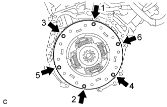
In several steps, uniformly install and tighten the 6 bolts in the sequence shown in the illustration.
- Torque:
- 30 N*m { 306 kgf*cm, 22 ft.*lbf }
Note
Take care not to insert the transmission input damper in a wrong direction.
-
-
INSTALL HYBRID VEHICLE TRANSAXLE ASSEMBLY
Tech Tips