HV RELAY ASSEMBLY INSTALLATION

-
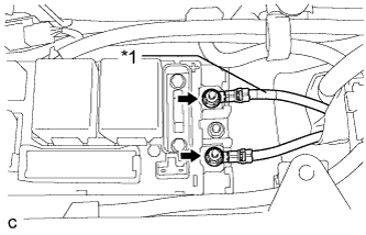
INSTALL HYBRID BATTERY JUNCTION BLOCK ASSEMBLY
CAUTION:
Be sure to wear insulated gloves and protective goggles.
-
Install the 2 bolts and EV battery fuse.
- Torque:
- 3.5 N*m { 36 kgf*cm, 31 in.*lbf }
Note
Be sure to use a torque wrench to tighten the nuts.
-
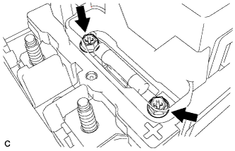
Install the hybrid battery junction block assembly with the 3 nuts.
- Torque:
- 7.5 N*m { 76 kgf*cm, 66 in.*lbf }
-
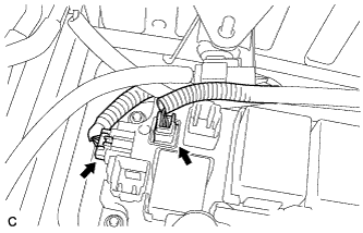
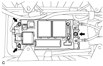
Connect the 2 connectors to the hybrid battery junction block assembly.
Note
Make sure that the connectors are fully engaged.
-
Connect the connector and 2 main battery cable connectors to the hybrid battery junction block assembly.
-
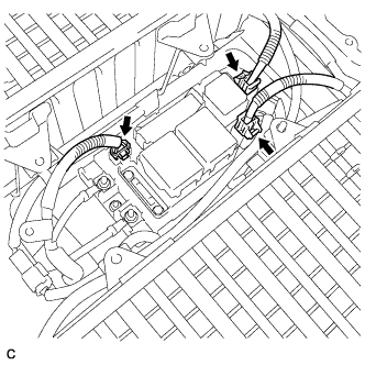
Text in Illustration *1 Red Tape Install the No. 3 wire frame to the hybrid battery junction block assembly with the 2 nuts.
- Torque:
- 9.0 N*m { 92 kgf*cm, 80 in.*lbf }
Note
-
Make sure that the ends of the No. 3 wire frame do not cross over each other.
-
Be sure to connect the No. 3 wire frame to each correct terminal as shown in the illustration.
-
-
CHECK HIGH VOLTAGE CABLE CONNECTION
CAUTION:
Wear insulated gloves and protective goggles.
-
Check that each wire harness is being installed securely.
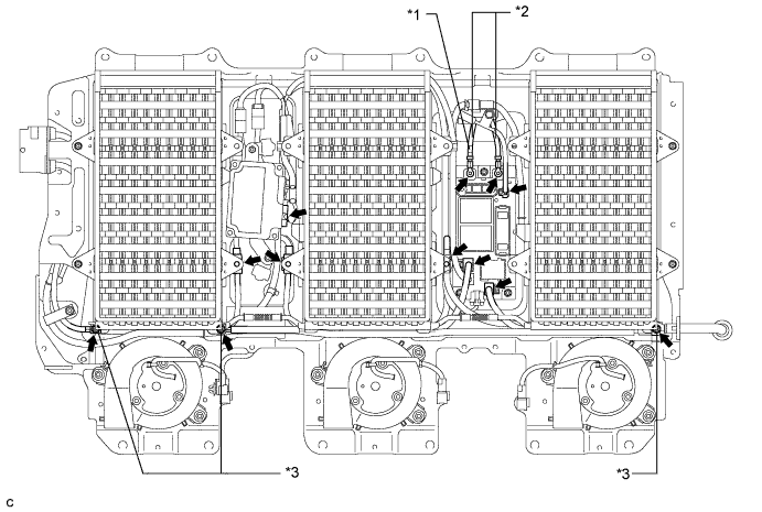
Text in Illustration *1 Red Tape *2 No. 3 Wire Frame *3 Plastic Cover - - Note
-
Make sure that the end of the No. 3 wire frame do not cross each other.
-
Be sure to connect the No. 3 wire frame to each correct terminal as shown in the illustration.
-
The connectors should be connected securely.
-
The nuts should be fastened securely.
-
Make sure that the 4 plastic covers are engaged securely.
-
-
-
INSTALL BATTERY COVER SUB-ASSEMBLY
Tech Tips
-
INSTALL SERVICE PLUG GRIP
CAUTION:
Wear insulated gloves.
Note
Before connecting the service plug, check that no parts and tools remain and that the high voltage terminals and connectors are connected securely.
-
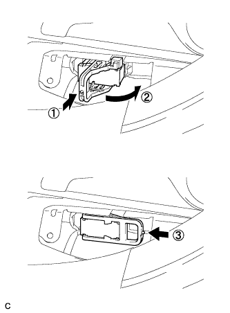
Wear insulated gloves and insert the service plug grip in the order shown in the illustration.
-
Tilt the service plug grip 90° and slide it down until a click sound is heard.
-
-
INSTALL BATTERY SERVICE HOLE COVER
-
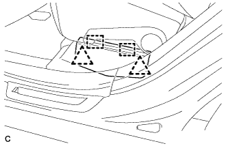
Engage the 2 clips, 2 guides and install the battery service hole cover.
Note
Make sure that the battery service hole cover is installed securely.
-
-
CONNECT CABLE TO NEGATIVE BATTERY TERMINAL
-
PERFORM INITIALIZATION
Some systems need initialization after reconnecting the cable to the negative battery terminal Click here.