CIRCUIT BREAKER SENSOR INSTALLATION

-
INSTALL NO. 1 CIRCUIT BREAKER SENSOR
-
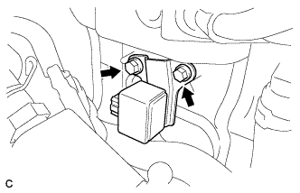
Install the No. 1 circuit breaker sensor with the 2 bolts to the inverter with converter assembly.
- Torque:
- 10 N*m { 102 kgf*cm, 7 ft.*lbf }
-
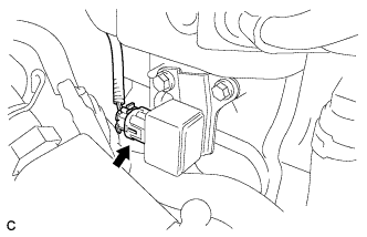
Connect the connector to the No. 1 circuit breaker sensor.
Note
The connectors should be connected securely.
-
-
INSTALL VACUUM SWITCHING VALVE
-
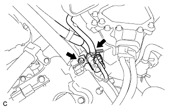
Install the bolt and vacuum switching valve.
- Torque:
- 10 N*m { 102 kgf*cm, 7 ft.*lbf }
-
Connect the connector and hose.
-
-
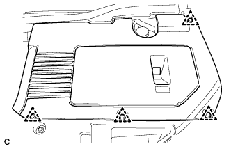
INSTALL V-BANK COVER SUB-ASSEMBLY
-
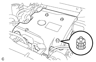
Fit the 4 retainers and install the V-bank cover sub-assembly.
-
-
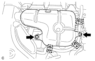
INSTALL INLET NO. 2 AIR CLEANER
-
Install the inlet No. 2 air cleaner with the 2 bolts.
- Torque:
- 8.0 N*m { 82 kgf*cm, 71 in.*lbf }
-
-
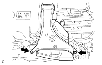
INSTALL INTAKE AIR RESONATOR SUB-ASSEMBLY
-
Install the intake air resonator sub-assembly with the 2 bolts.
- Torque:
- 8.0 N*m { 82 kgf*cm, 71 in.*lbf }
-
Connect the 3 water hose clamps to the intake air resonator sub-assembly.
-
-
INSTALL COOL AIR INTAKE DUCT SEAL
-
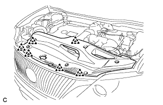
Install the cool air intake duct seal with the 6 clips.
-
-
INSTALL ENGINE ROOM SIDE COVER
-
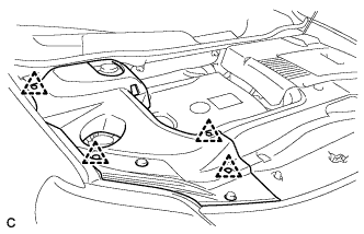
Install the engine room side cover with the 4 clips.
-
-
INSTALL ENGINE ROOM SIDE COVER LH
-
Install the engine room side cover with the 4 clips.
-
-
CONNECT CABLE TO NEGATIVE BATTERY TERMINAL
-
PERFORM INITIALIZATION
Some systems need initialization after reconnecting the cable to the negative battery terminal Click here.