CIRCUIT BREAKER SENSOR REMOVAL

-
DISCONNECT CABLE FROM NEGATIVE BATTERY TERMINAL
Note
When disconnecting the cable, some systems need to be initialized after the cable is reconnected Click here.
-
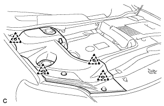
REMOVE ENGINE ROOM SIDE COVER LH
-
Remove the 4 clips and engine room side cover LH.
-
-
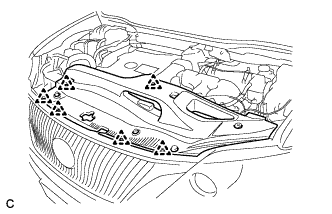
REMOVE ENGINE ROOM SIDE COVER
-
Remove the 4 clips and engine room side cover.
-
-
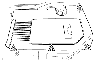
REMOVE COOL AIR INTAKE DUCT SEAL
-
Remove the 6 clips and cool air intake duct seal.
-
-
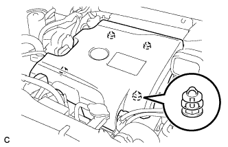
REMOVE INTAKE AIR RESONATOR SUB-ASSEMBLY
-
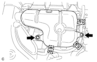
Remove the 3 clamps and Disconnect the water hose from the intake air resonator sub-assembly.
-
Remove the 2 bolts and intake air resonator sub-assembly from the inverter with converter assembly.
-
-
REMOVE INLET NO. 2 AIR CLEANER
-
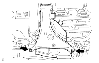
Remove the 2 bolts and inlet No. 2 air cleaner.
-
-
REMOVE V-BANK COVER SUB-ASSEMBLY
-
Hold the front of the V-bank cover sub-assembly and raise it to disengage the 2 retainers on the front of the V-bank cover sub-assembly. Continue to raise the V-bank cover sub-assembly to disengage the 2 retainers on the rear of the V-bank cover sub-assembly and remove the V-bank cover sub-assembly.
Note
Attempting to disengage both front and rear retainers at the same time may cause the V-bank cover sub-assembly to break.
-
-
SEPARATE VACUUM SWITCHING VALVE
-
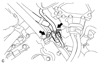
Disconnect the connector and hose.
-
Remove the bolt, and separate the vacuum switching valve.
-
-
REMOVE NO. 1 CIRCUIT BREAKER SENSOR
-
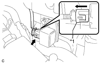
Text in Illustration *1 Outer Section Move the outer section to the wire harness side as illustrated, then disconnect the No. 1 circuit breaker sensor connector.
-
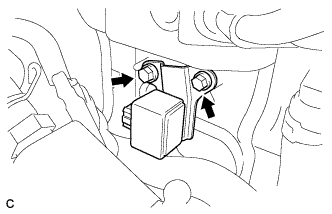
Remove the 2 bolts and No. 1 circuit breaker sensor from the inverter with converter assembly.
-