CAMSHAFT REMOVAL

-
REMOVE HYBRID VEHICLE TRANSAXLE ASSEMBLY
Tech Tips
-
REMOVE TRANSMISSION INPUT DAMPER ASSEMBLY
-
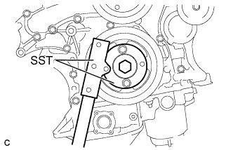
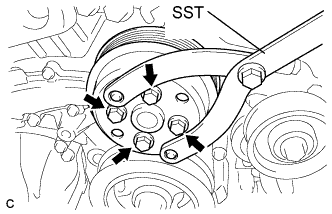
Using SST, hold the crankshaft pulley.
- SST
- 09213-70011 ( 09213-70020 )
- 09330-00021
-
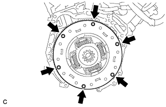
Remove the 6 bolts and transmission input damper assembly from the flywheel sub-assembly.
-
-
REMOVE FLYWHEEL SUB-ASSEMBLY
-
Using SST, hold the crankshaft pulley.
- SST
- 09213-70011 ( 09213-70020 )
- 09330-00021
-
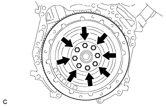
Remove the 8 bolts and flywheel sub-assembly.
-
-
INSTALL ENGINE ON ENGINE STAND
-
Install the engine onto an engine stand with the bolts.
-
-
REMOVE ENGINE HANGERS
-
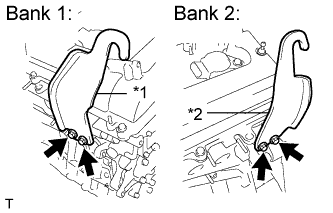
Text in Illustration *1 No. 1 Engine Hanger *2 No. 2 Engine Hanger Remove the 4 bolts and 2 engine hangers.
-
-
REMOVE INTAKE AIR SURGE TANK ASSEMBLY
-
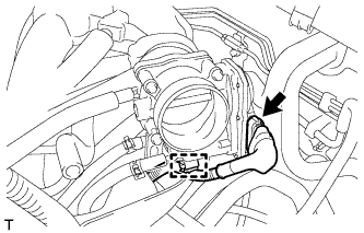
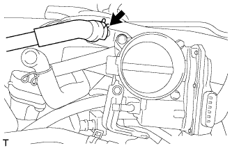
Disconnect the throttle body assembly connector and wire harness clamp.
-
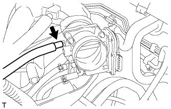
Disconnect the fuel vapor feed hose.
-
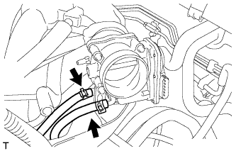
Disconnect the 2 water by-pass hoses.
-
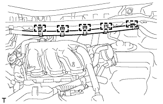
Disconnect the 5 clamps and separate the main wire.
-
Disconnect the ventilation hose.
-
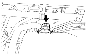
Disconnect the connector from the manifold absolute pressure sensor.
-

Remove the bolt and separate the No. 1 surge tank stay from the intake air surge tank assembly.
-
Remove the bolt and separate the throttle body bracket from the intake air surge tank assembly.
-
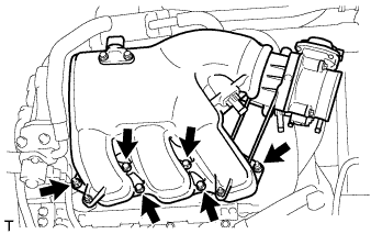
Remove the 2 nuts from the intake air surge tank assembly.
-
Using a 5 mm socket hexagon wrench, remove the 4 bolts.
-
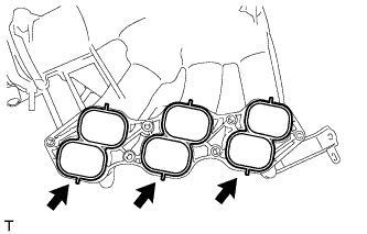
Remove the intake air surge tank assembly and 3 air surge tank to intake manifold gaskets.
-
-
REMOVE THROTTLE BODY BRACKET
-
Remove the bolt and throttle body bracket.
-
-
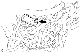
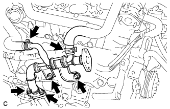
REMOVE NO. 2 EGR PIPE
-
Remove the 2 nuts, 2 bolts, No. 2 EGR pipe and 2 gaskets. (Type A)
-
Remove the 2 nuts, 2 bolts, No. 2 EGR pipe and 2 gaskets. (Type B)
-
-
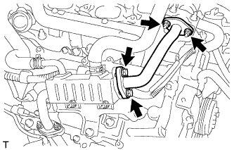
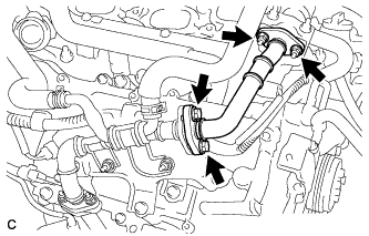
REMOVE EGR COOLER ASSEMBLY
-
Type A:
-
Disconnect the 2 water hoses.
-
Remove the 4 nuts, EGR cooler assembly and gasket.
-
-
Type B:
-
Disconnect the 2 water hoses.
-
Remove the 4 nuts, EGR cooler assembly and gasket.
-
-
-
REMOVE NO. 1 EGR COOLER BRACKET
-
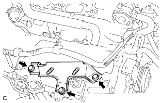
Remove the 3 bolts and No. 1 EGR cooler bracket.
-
-
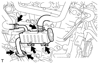
REMOVE EGR DELIVERY CHAMBER
-
Disconnect the 2 water hoses and connector.
-
Remove the EGR delivery chamber.
-
Remove the No. 2 intake manifold gasket.
-
-
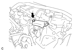
REMOVE NO. 1 SURGE TANK STAY
-
Remove the bolt and No. 1 surge tank stay.
-
-
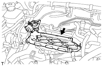
REMOVE IGNITION COIL ASSEMBLY
-
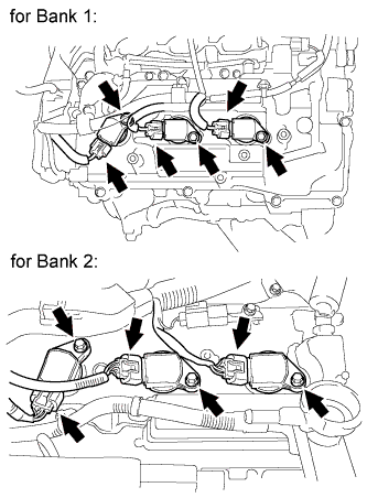
Disconnect the 6 ignition coil connectors.
-
Remove the 6 bolts and 6 ignition coils.
-
-
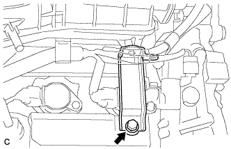
REMOVE NO. 2 ENGINE MOUNTING STAY RH
-
Remove the bolt and No. 2 engine mounting stay RH.
-
-
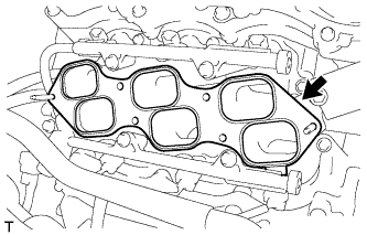
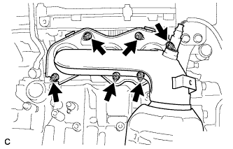
REMOVE INTAKE MANIFOLD
-
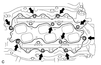
Uniformly loosen and remove the 6 bolts and 4 nuts.
-
Remove the intake manifold and 2 gaskets.
-
-
REMOVE EXHAUST MANIFOLD SUB-ASSEMBLY RH
-
Uniformly loosen and remove the 6 nuts.
-
Remove the exhaust manifold sub-assembly RH and gasket.
-
-
REMOVE NO. 2 ENGINE OIL LEVEL DIPSTICK GUIDE
-
Remove the engine oil level dipstick.
-
Remove the bolt and No. 2 engine oil level dipstick guide.
-
Remove the O-ring from the No. 2 engine oil level dipstick guide.
-
-
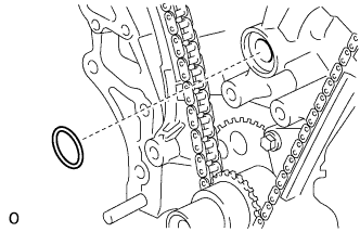
REMOVE ENGINE OIL LEVEL DIPSTICK GUIDE
-
Remove the bolt and engine oil level dipstick guide.
-
Remove the O-ring.
-
-
REMOVE NO. 2 MANIFOLD STAY
-
Remove the bolt, nut and No. 2 manifold stay.
-
-
REMOVE NO. 2 EXHAUST MANIFOLD HEAT INSULATOR
-
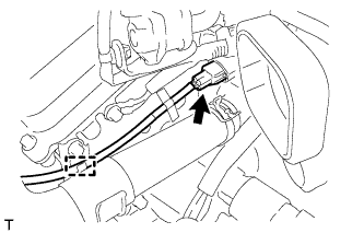
Disconnect the air fuel ratio sensor connector (for Bank 2 Sensor 1).
-
Disconnect the sensor wire from the radiator pipe clamp.
-
Remove the 3 bolts and No. 2 exhaust manifold heat insulator.
-
-
REMOVE EXHAUST MANIFOLD SUB-ASSEMBLY LH
-
Uniformly loosen and remove the 6 nuts.
-
Remove the exhaust manifold sub-assembly LH and gasket.
-
-
REMOVE V-RIBBED BELT TENSIONER ASSEMBLY
-
Remove the 5 bolts and V-ribbed belt tensioner assembly.
-
-
REMOVE NO. 2 TIMING GEAR COVER
-
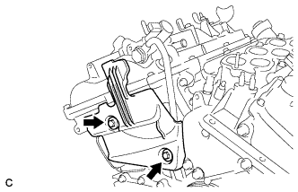
Remove the 2 bolts and No. 2 timing gear cover.
-
-
REMOVE WATER PUMP PULLEY
-
Using SST, hold the water pump pulley.
- SST
- 09960-10010 ( 09962-01000, 09963-00700 )
-
Remove the 4 bolts and water pump pulley.
-
-
REMOVE RADIO SETTING CONDENSER
-
Remove the 2 bolts and 2 radio setting condensers.
-
-
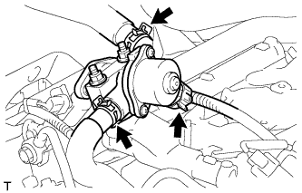
REMOVE NO. 1 VACUUM SWITCHING VALVE
-
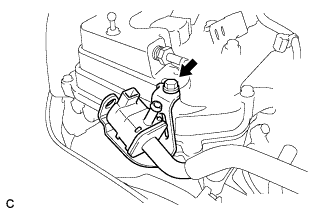
Remove the bolt and No. 1 vacuum switching valve.
-
-
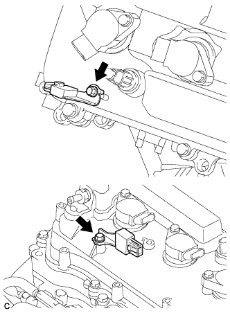
REMOVE CRANK POSITION SENSOR
-
Disconnect the crank position sensor connector.
-
Remove the bolt and crank position sensor.
-
-
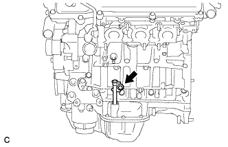
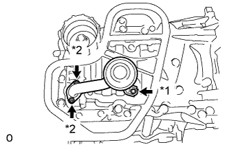
REMOVE NO. 1 OIL PIPE
-
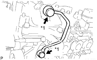
Text in Illustration *1 Oil Pipe Union Remove the 2 oil pipe unions, gaskets and No. 1 oil pipe.
-
Remove the oil control valve filter LH and gaskets.
-
-
REMOVE OIL PIPE
-
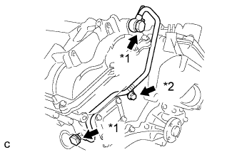
Text in Illustration *1 Oil Pipe Union *2 Bolt Remove the bolt.
-
Remove the 2 oil pipe unions and oil pipe.
-
Remove the oil control valve filter RH and gaskets.
-
-
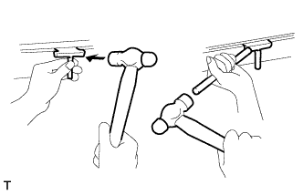
REMOVE CRANKSHAFT PULLEY
-
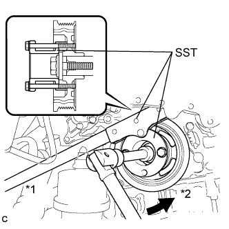
Text in Illustration *1 Hold *2 Turn Using SST, loosen the crankshaft pulley bolt.
- SST
- 09213-70011 ( 09213-70020 )
- 09330-00021
-
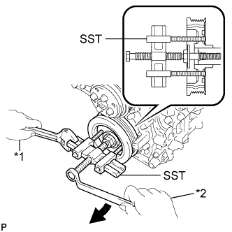
Text in Illustration *1 Hold *2 Turn Using SST, remove the crankshaft pulley bolt and crankshaft pulley.
- SST
- 09950-50013 ( 09951-05010, 09952-05010, 09953-05020, 09954-05021 )
-
-
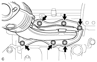
REMOVE FRONT NO. 1 ENGINE MOUNTING BRACKET LH
-
Remove the 6 bolts and front No. 1 engine mounting bracket LH.
-
Using an E8 "TORX" socket wrench, remove the 2 stud bolts.
-
-
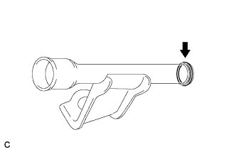
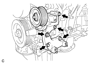
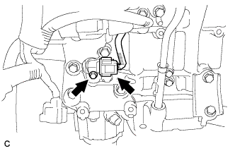
REMOVE INLET WATER HOUSING
-
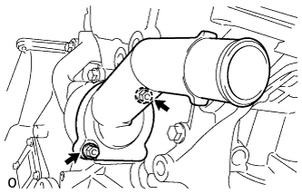
Remove the 2 nuts, inlet water and thermostat.
-
Remove the gasket.
-
Remove the 2 stud bolts.
-
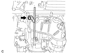
Separate the No. 1 water by-pass hose from the inlet water housing.
-
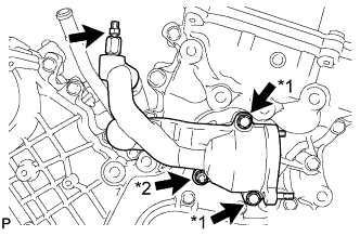
Text in Illustration *1 Bolt *2 Nut Remove the drain cock plug.
-
Remove the drain cock assembly.
-
Remove the 2 bolts, nut and inlet water housing.
-
Remove the 2 O-rings.
-
-
REMOVE CYLINDER HEAD COVER SUB-ASSEMBLY
-
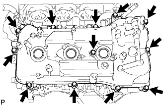
Remove the 12 bolts, seal washer, cylinder head cover sub-assembly and cylinder head cover gasket.
-
Remove the 3 gaskets.
-
-
REMOVE CYLINDER HEAD COVER SUB-ASSEMBLY LH
-
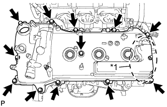
Text in Illustration *1 Baffle Plate Remove the 12 bolts, seal washer, cylinder head cover sub-assembly LH and cylinder head cover gasket.
Note
The baffle plate is located on the back of the portion shown in the illustration. Do not damage the baffle plate when removing the cylinder head cover sub-assembly LH.
-
Remove the 3 gaskets.
-
-
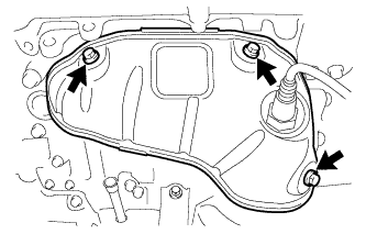
REMOVE NO. 2 OIL PAN SUB-ASSEMBLY
-
Text in Illustration *1 Nut Remove the 16 bolts and 2 nuts.
-
Insert the blade of the oil pan seal cutter between the oil pans. Cut through the applied sealer and remove the No. 2 oil pan sub-assembly.
Note
Be careful not to damage the contact surfaces of the oil pans.
-
Using an E6 "TORX" socket wrench, remove the 2 stud bolts.
-
-
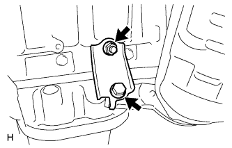
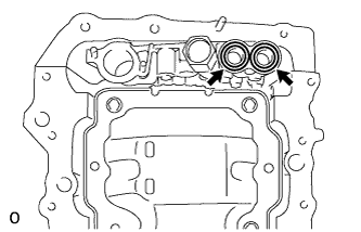
REMOVE OIL STRAINER SUB-ASSEMBLY
-
Text in Illustration *1 Bolt *2 Nut Remove the bolt, 2 nuts, oil strainer sub-assembly and gasket.
-
Using an E6 "TORX" socket wrench, remove the 2 stud bolts.
-
-
REMOVE OIL PAN SUB-ASSEMBLY
-
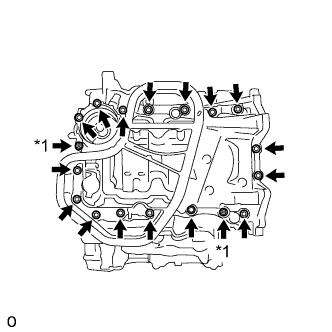
Text in Illustration *1 Nut Remove the 16 bolts and 2 nuts.
Tech Tips
Be sure to clean the bolts and stud bolts and check the threads for cracks or other damage.
-
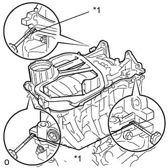
Text in Illustration *1 Protective Tape Remove the oil pan sub-assembly by prying between the oil pan sub-assembly and cylinder block sub-assembly with a screwdriver.
Note
Be careful not to damage the contact surfaces of the cylinder block and oil pan.
Tech Tips
Tape the screwdriver tip before use.
-
Remove the 2 O-rings.
-
Using an E8 "TORX" socket wrench, remove the 2 stud bolts.
-
-
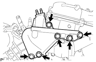
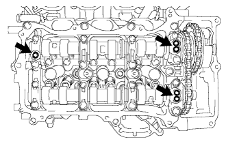
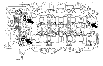
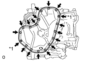
REMOVE TIMING CHAIN COVER SUB-ASSEMBLY
-
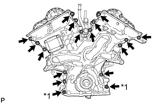
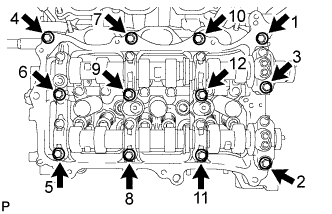
Text in Illustration *1 Nut Remove the 15 bolts and 2 nuts as shown in the illustration.
-
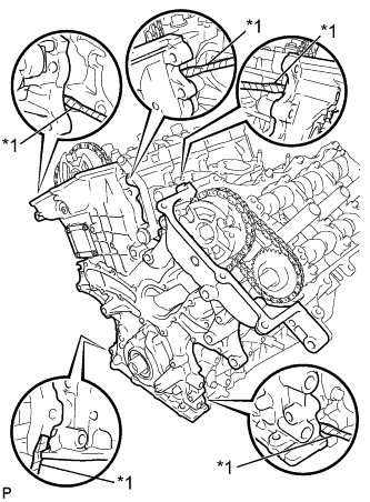
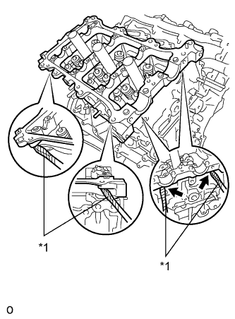
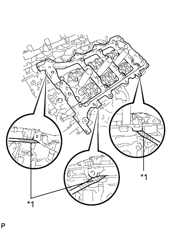
Text in Illustration *1 Protective Tape Remove the timing chain cover sub-assembly by prying between the timing chain cover and cylinder head sub-assembly or cylinder block sub-assembly with a screwdriver.
Note
Be careful not to damage the contact surfaces of the cylinder head, cylinder block and chain cover.
Tech Tips
Tape the screwdriver tip before use.
-
Remove the 4 bolts, chain cover plate and chain cover plate gasket.
-
Remove the gasket.
-
-
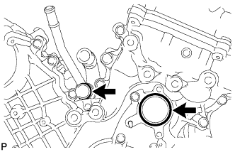
REMOVE TIMING CHAIN CASE OIL SEAL
-
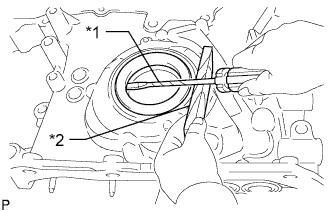
Text in Illustration *1 Protective Tape *2 Wooden Block Using a screwdriver, pry out the timing chain case oil seal.
Tech Tips
Tape the screwdriver tip before use.
-
-
SET NO. 1 CYLINDER TO TDC / COMPRESSION
-
Temporarily tighten the pulley set bolt.
-
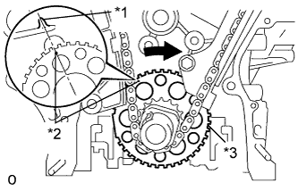
Text in Illustration *1 Center Line *2 Timing Mark *3 Sensor Plate Turn the crankshaft clockwise to align the timing mark on the crank angle sensor plate with the RH block bore center line (TDC/compression).
-
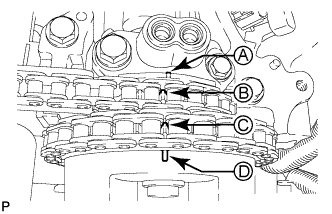
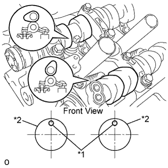
Check that the timing marks of the camshaft timing gears are aligned with the timing marks of the bearing cap as shown in the illustration.
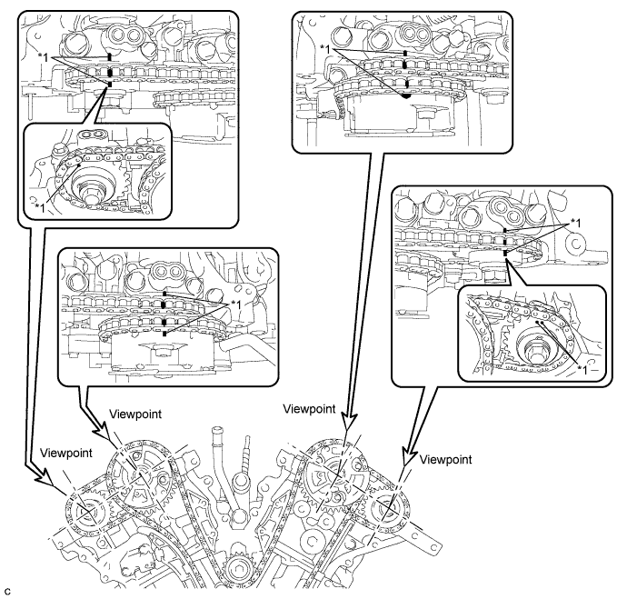
Text in Illustration *1 Timing Mark - - Tech Tips
For the intake camshaft:
Be sure to check mark A at the point when marks B, C, and D are positioned in line. If the marks are checked from any other viewpoint, they cannot be checked correctly.
If not, turn the crankshaft clockwise 1 revolution (360°) and align the timing marks as above.
-
-
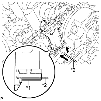
REMOVE NO. 1 CHAIN TENSIONER ASSEMBLY
-
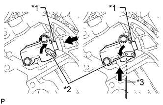
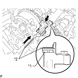
Text in Illustration *1 Plunger *2 Stopper Plate *3 Pin Move the stopper plate upward to release the lock, and push the plunger deep into the tensioner.
-
Move the stopper plate downward to set the lock, and insert a pin of 1.27 mm diameter (0.0500 in.) into the stopper plate hole.
-
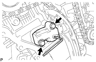
Remove the 2 bolts and No. 1 chain tensioner assembly.
-
-
REMOVE CHAIN TENSIONER SLIPPER
-
Remove the chain tensioner slipper.
-
-
REMOVE CHAIN SUB-ASSEMBLY
-
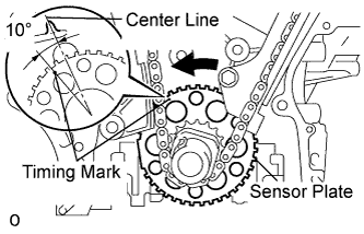
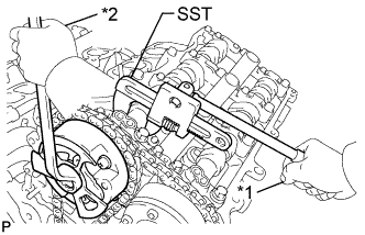
Turn the crankshaft counterclockwise 10° to loosen the chain of the crankshaft timing sprocket.
-
Remove the pulley set bolt.
-
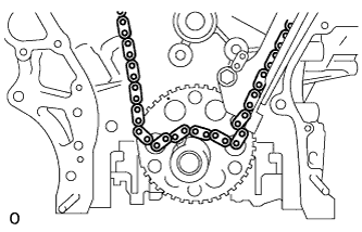
Remove the chain sub-assembly from the crankshaft timing sprocket and place it on the crankshaft.
-
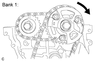
Turn the camshaft timing gear assembly on bank 1 clockwise (approximately 60°) and set it as shown in the illustration. Be sure to loosen the chain sub-assembly between the banks.
-
Remove the chain sub-assembly.
-
-
REMOVE IDLE SPROCKET ASSEMBLY
-
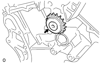
Using a 10 mm hexagon wrench, remove the No. 2 idle gear shaft, idle sprocket assembly and No. 1 idle gear shaft.
-
-
REMOVE CAMSHAFT TIMING GEARS AND NO. 2 CHAIN (for Bank 1)
-
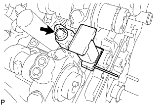
Text in Illustration *1 Plunger *2 Pin While raising the No. 2 chain tensioner assembly, insert a pin of 1.0 mm (0.0394 in.) diameter into the hole to hold the No. 2 chain tensioner assembly.
-
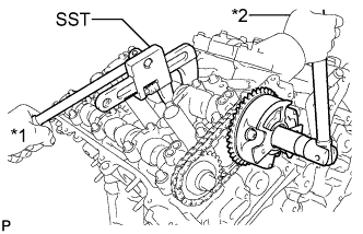
Text in Illustration *1 Hold *2 Turn Using SST to hold the hexagonal portion of each camshaft, loosen the bolts of the camshaft timing gear assembly and the camshaft timing sprocket.
- SST
- 09922-10010
Note
Do not loosen the other bolts. If any of the bolts is loosened, replace the camshaft timing gear assembly and/or the camshaft timing exhaust gear assembly with a new one.
-
Remove the 2 bolts and the camshaft timing gear assembly together with the No. 2 chain.
-
-
REMOVE NO. 2 CHAIN TENSIONER ASSEMBLY
-
Remove the bolt and No. 2 chain tensioner assembly.
-
-
REMOVE CAMSHAFT BEARING CAP (for Bank 1)
-
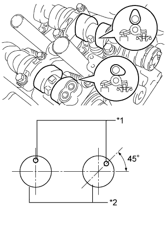
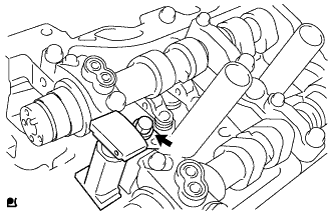
Text in Illustration *1 Knock Pin *2 Camshaft Check that the camshafts are positioned as shown in the illustration.
-
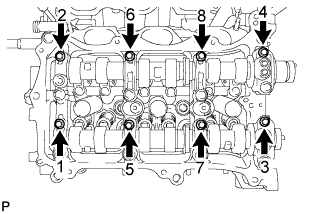
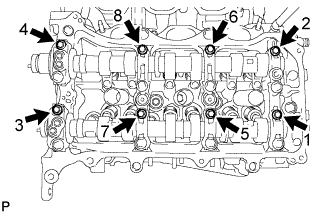
Uniformly loosen and remove the 8 bearing cap bolts in several steps and in the sequence shown in the illustration.
-
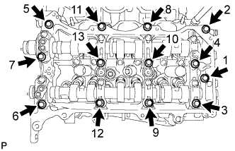
Uniformly loosen and remove the 12 bearing cap bolts in several steps and in the sequence shown in the illustration.
Note
Uniformly loosen the bolts while keeping the camshaft level.
Tech Tips
Arrange the removed parts in the correct order.
-
Remove the 5 camshaft bearing caps.
-
-
REMOVE CAMSHAFT
-
Remove the camshaft.
-
-
REMOVE NO. 2 CAMSHAFT
-
Remove the No. 2 camshaft.
-
-
REMOVE CAMSHAFT HOUSING SUB-ASSEMBLY RH
-
Text in Illustration *1 Protective Tape Remove the camshaft housing sub-assembly RH by prying between the cylinder head and camshaft housing sub-assembly RH with a screwdriver.
Note
Be careful not to damage the contact surfaces of the cylinder head and camshaft housing sub-assembly RH.
Tech Tips
Tape the screwdriver tip before use.
-
-
REMOVE CAMSHAFT TIMING GEARS AND NO. 2 CHAIN (for Bank 2)
-
Text in Illustration *1 Plunger *2 Pin While pushing down the No. 3 chain tensioner assembly, insert a pin of 1.0 mm (0.0394 in.) diameter into the hole to hold the No. 3 chain tensioner assembly.
-
Text in Illustration *1 Hold *2 Turn Using SST to hold the hexagonal portion of each camshaft, loosen the bolts of the camshaft timing gear assembly and the camshaft timing sprocket.
- SST
- 09922-10010
Note
Do not loosen the other bolts. If any of the bolts is loosened, replace the camshaft timing gear assembly and/or the camshaft timing exhaust gear assembly with a new one.
-
Remove the 2 bolts and the camshaft timing gear together with the No. 2 chain.
-
-
REMOVE NO. 3 CHAIN TENSIONER ASSEMBLY
-
Remove the bolt and No. 3 chain tensioner assembly.
-
-
REMOVE CAMSHAFT BEARING CAP (for Bank 2)
-
Text in Illustration *1 Knock Pin *2 Camshaft Check that the camshafts are positioned as shown in the illustration.
-
Uniformly loosen and remove the 8 bearing cap bolts in several steps and in the sequence shown in the illustration.
-
Uniformly loosen and remove the 13 bearing cap bolts in several steps and in the sequence shown in the illustration.
Note
Uniformly loosen the bolts while keeping the camshaft level.
Tech Tips
Arrange the removed parts in the correct order.
-
Remove the 5 camshaft bearing caps.
-
-
REMOVE NO. 3 CAMSHAFT SUB-ASSEMBLY
-
Remove the No. 3 camshaft sub-assembly.
-
-
REMOVE NO. 4 CAMSHAFT SUB-ASSEMBLY
-
Remove the No. 4 camshaft sub-assembly.
-
-
REMOVE CAMSHAFT HOUSING SUB-ASSEMBLY LH
-
Text in Illustration *1 Protective Tape Remove the camshaft housing sub-assembly LH by prying between the cylinder head and camshaft housing sub-assembly LH with a screwdriver.
Note
Be careful not to damage the contact surfaces of the cylinder head and camshaft housing sub-assembly LH.
Tech Tips
Tape the screwdriver tip before use.
-
-
INSPECT CAMSHAFT TIMING GEAR ASSEMBLY
-
Clamp the camshaft in a vise.
Note
Be careful not to damage the camshaft in the vise.
-
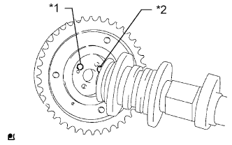
Text in Illustration *1 Key Groove *2 Straight Pin Put the camshaft timing gear assembly and camshaft together by aligning the key groove and straight pin.
-
Lightly press and turn the camshaft timing gear assembly against the camshaft, and press harder after the pin enters the groove.
Note
Be sure not to turn the camshaft timing gear assembly in the retard direction.
-
Check that there is no clearance between the camshaft timing gear assembly flange and the camshaft.
-
Tighten the flange bolt while holding the camshaft.
- Torque:
- 100 N*m { 1020 kgf*cm, 74 ft.*lbf }
-
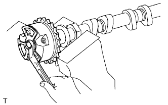
Check the lock of the camshaft timing gear assembly.
-
Clamp the camshaft in a vise, and confirm that the camshaft timing gear assembly is locked.
Note
Be careful not to damage the camshaft.
-
-
Release the lock pin.
-
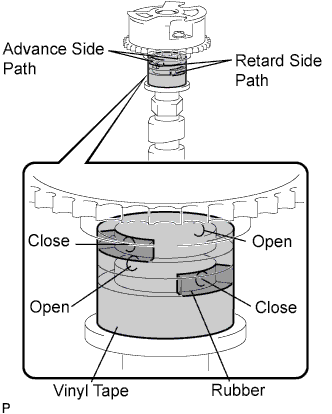
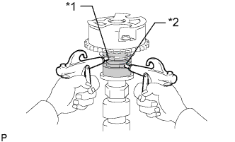
Cover the 4 oil paths of the cam journal with vinyl tape as shown in the illustration.
Tech Tips
The 2 advance side paths are located in the camshaft groove. Plug one of the paths with a rubber piece.
-
Break through the tape on the advance side path and the retard side path on the opposite side of the hole of the advance side path, as shown in the illustration.
-
Text in Illustration *1 Advanced Side Path *2 Retard Side Path Apply approximately 200 kPa (2.0 kgf/cm2, 28 psi) of air pressure to the 2 opened paths.
CAUTION:
Cover the paths with a piece of cloth when applying pressure to prevent oil from spraying.
-
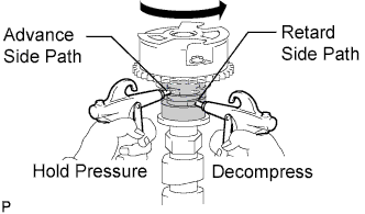
Check that the camshaft timing gear assembly rotates in the advance direction when reducing the air pressure applied to the retard side path.
Tech Tips
This operation releases the lock pin at the most retarded position.
-
When the camshaft timing gear assembly reaches the most advanced position, release the air pressure first from the retard side path and next from the advance side path.
Note
Do not release the air pressure from the advance side path first. The gear may abruptly shift in the retard direction and break the lock pin.
-
-
Check for smooth rotation.
-
Turn the camshaft timing gear assembly within its movable range (21°) 2 or 3 times, but do not turn it to the most retarded position. Make sure that the gear turns smoothly.
Note
Do not use air pressure to perform the smooth operation check.
-
-
Check the lock in the most retarded position.
-
Confirm that the camshaft timing gear assembly locks at the most retarded position.
-
-
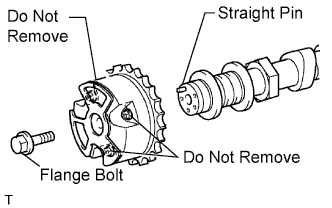
Remove the flange bolt and camshaft timing gear assembly.
Note
-
Do not remove the other 3 bolts.
-
If planning to reuse the camshaft timing gear, be sure to release the straight pin lock before installing the camshaft timing gear.
-
-