FRAME WIRE REMOVAL

-
PRECAUTION
Tech Tips
-
REMOVE FRONT DECK FLOOR BOX
Tech Tips
-
DISCONNECT CABLE FROM BATTERY TERMINAL
Note
When disconnecting the cable, some systems need to be initialized after the cable is reconnected Click here.
-
Disconnect the negative battery terminal.
-
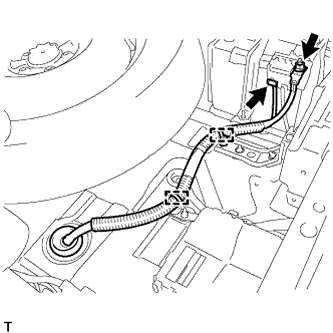
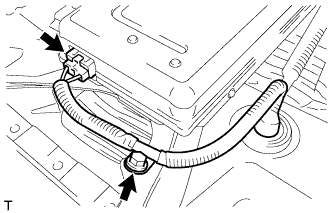
Remove the nut, and disconnect the connector.
-
Disconnect the 2 clamps, and disconnect the No. 3 wire frame.
-
-
REMOVE BATTERY SERVICE HOLE COVER
-
Disengage the 2 clips and 2 guides, and remove the battery service hole cover.
Tech Tips
Because these are 2-piece clips, one side will remain in the bracket when they are being removed.
-
-
REMOVE SERVICE PLUG GRIP
CAUTION:
-
Remove the service plug grip to interrupt a high voltage circuit at the time of the check.
-
Keep the removed service plug grip in your pocket to prevent other technicians from accidentally reconnecting it while you are servicing the vehicle.
-
All the high voltage wiring connectors are orange colored.
-
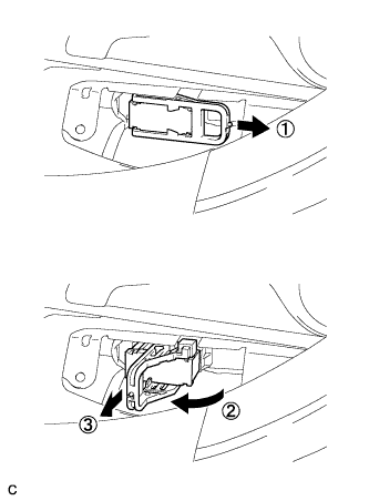
Wear insulated gloves. Remove the service plug grip after sliding the lever of the service plug grip.
CAUTION:
-
Keep the removed service plug grip in your pocket to prevent other technicians from accidentally reconnecting it while you are servicing the vehicle.
-
After disconnecting the service plug grip, wait for at least 10 minutes before touching any of the high-voltage connectors or terminals.
Tech Tips
Waiting for at least 10 minutes is required to discharge the high-voltage capacitor inside the inverter with converter assembly.
-
-
-
REMOVE INVERTER WITH CONVERTER ASSEMBLY
Tech Tips
-
REMOVE INVERTER TRAY BRACKET SUB-ASSEMBLY
-
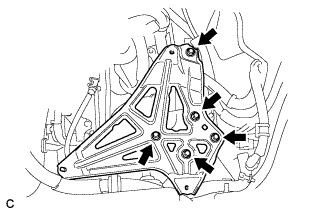
Remove the 5 bolts and inverter tray bracket sub-assembly.
-
-
REMOVE EXHAUST MANIFOLD SUB-ASSEMBLY RH
Tech Tips
-
REMOVE FUEL TANK ASSEMBLY
Tech Tips
-
REMOVE FRONT SEAT ASSEMBLY
Tech Tips
-
REMOVE REAR SEAT ASSEMBLY RH
Tech Tips
-
REMOVE REAR SEAT ASSEMBLY LH
Tech Tips
-
REMOVE REAR CONSOLE BOX ASSEMBLY
Tech Tips
-
REMOVE FRONT DOOR SCUFF PLATE LH
-
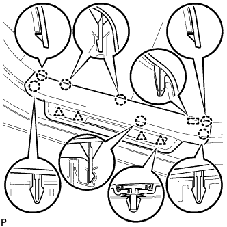
Disengage the 7 claws, 4 clips and guide, and remove the front door scuff plate LH.
Tech Tips
A part of the clip remains on the vehicle side.
-
w/ Illumination:
-
Disconnect the connector.
-
-
-
REMOVE REAR DOOR SCUFF PLATE LH
-
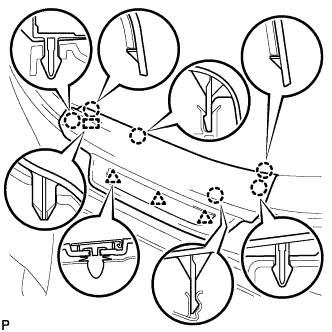
Disengage the 6 claws, 3 clips and guide, and remove the rear door scuff plate LH.
-
-
REMOVE LOWER CENTER PILLAR GARNISH LH
-
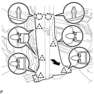
Disengage the 2 claws and 5 clips, and remove the lower center pillar garnish LH.
-
-
REMOVE FRONT DOOR SCUFF PLATE RH
Tech Tips
Perform the same procedure as for the LH side.
-
REMOVE REAR DOOR SCUFF PLATE RH
Tech Tips
Perform the same procedure as for the LH side.
-
REMOVE LOWER CENTER PILLAR GARNISH RH
Tech Tips
Perform the same procedure as for the LH side.
-
REMOVE REAR SEAT SIDE COVER LH
-
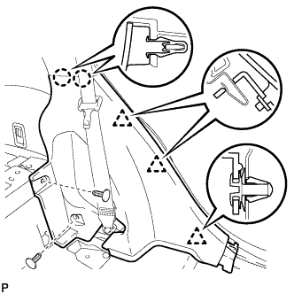
Remove the 2 clips.
-
Disengage the 2 claws and 3 clips, and remove the rear seat side cover LH.
Tech Tips
A part of the clip remains on the vehicle side.
-
-
REMOVE REAR SEAT SIDE COVER RH
Tech Tips
Perform the same procedure as for the LH side.
-
REMOVE AIR INTAKE COVER
-
Remove the air intake cover LH.
-
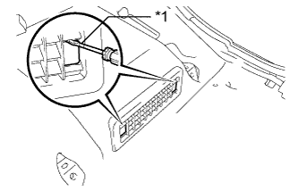
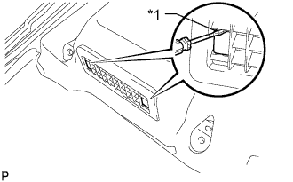
Text in Illustration *1 Protective Tape Release the claw by using a screwdriver with the tip taped, and remove its 2 hole covers.
-
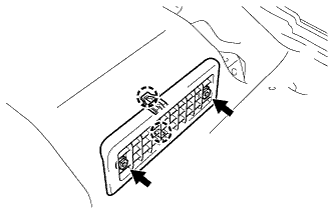
Remove the 2 screws, then release the 2 claws and remove the air intake cover LH.
-
-
Remove the air intake cover CTR.
-
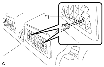
Text in Illustration *1 Protective Tape Release the claw by using a screwdriver with the tip taped, and remove its 2 hole covers.
-
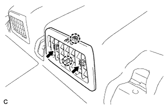
Remove the 2 screws, then release the 2 claws and remove the center air intake cover.
-
-
Remove the air intake cover RH.
-
Text in Illustration *1 Protective Tape Release the claw by using a screwdriver with its tip taped, and remove the 2 hole covers.
-

Remove the 2 screws, then release the 2 claws and remove the air intake cover RH.
-
-
-
REMOVE FRONT FLOOR CARPET ASSEMBLY
-
Turn back the front floor carpet assembly.
-
-
REMOVE NO. 1 BATTERY COVER LID
CAUTION:
Be sure to wear insulated gloves and protective goggles.
-
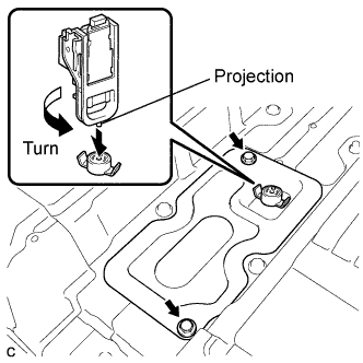
Using the service plug grip, remove the No. 1 battery cover lid.
Tech Tips
Insert the projection part of the service plug grip, and turn the button of the battery cover lock striker counterclockwise, and release the lock.
-
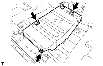
Remove the 2 bolts and battery service hole cover.
-
-
DISCONNECT HYBRID BATTERY JUNCTION BLOCK ASSEMBLY
CAUTION:
Wear insulating gloves.
Note
Insulate the removed terminals with insulating tape.
-
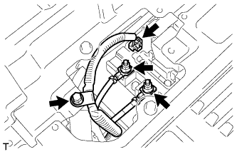
Remove the bolt, and disconnect the No. 3 wire frame from the battery cover sub-assembly.
-
Disconnect the No. 3 wire frame from the hybrid battery junction block.
-
Remove the 2 nuts, and disconnect the No. 3 wire frame from the hybrid battery junction block.
-
-
REMOVE NO. 1 POWER STEERING BRACKET
-
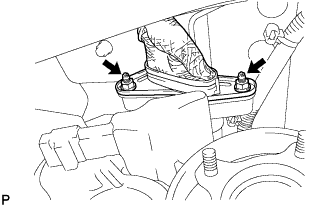
Remove the 3 nuts and No. 1 power steering bracket.
-
-
DISCONNECT POWER STEERING CONVERTER ASSEMBLY
CAUTION:
Wear insulating gloves.
Note
Insulate the removed terminals with insulating tape.
-
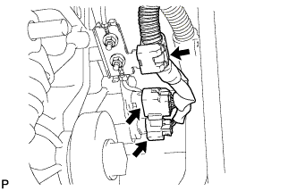
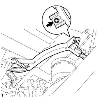
Remove the bolt, and disconnect the connector from the power steering converter assembly.
-
Remove the bolt, clamp, and disconnect the connector from the power steering converter assembly.
-
-
DISCONNECT REAR TRACTION MOTOR WITH TRANSAXLE ASSEMBLY (for AWD)
CAUTION:
Wear insulating gloves.
Note
Insulate the removed terminals with insulating tape.
-
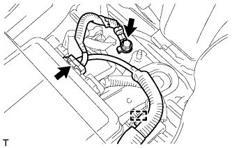
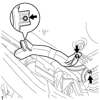
Disconnect the 2 connectors and clamp from the rear traction motor with transaxle assembly.
-
Remove the 2 nuts, and disconnect the No. 3 wire frame from the rear traction motor with transaxle assembly.
Note
Cover the hole where the cable was connected with tape or equivalent (non-residue type) to prevent entry of foreign matter.
-
-
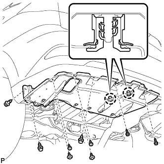
REMOVE NO. 6 WIRING HARNESS PROTECTOR
-
Remove the 4 nuts and No. 6 wiring harness protector.
-
-
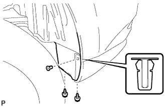
REMOVE REAR QUARTER PANEL MUDGUARD SUB-ASSEMBLY LH (w/ Active Stabilizer System)
-
Remove the rear quarter panel mudguard sub-assembly Click here.
Tech Tips
This step is not necessary for vehicles without the rear fender mudguard.
-
-
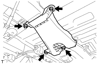
REMOVE NO. 2 LUGGAGE COMPARTMENT SIDE COVER PROTECTOR (w/ Active Stabilizer System)
-
Remove the 2 screws and grommet.
-
Remove the 4 screws.
-
Remove the 2 bolts and 3 clips.
-
Disengage the 2 claws and remove the No. 2 luggage compartment side cover protector.
-
-
REMOVE NO. 3 WIRE FRAME
CAUTION:
Wear insulating gloves.
Note
Insulate the removed terminals with insulating tape.
-
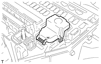
Remove the No. 3 relay block cover.
-
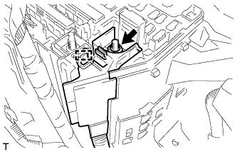
Remove the nut and clamp from engine room junction block assembly.
-
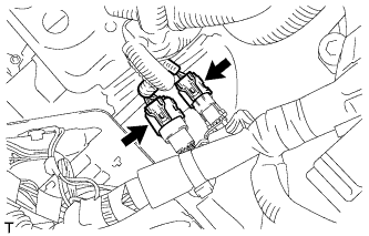
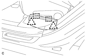
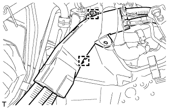
Disconnect the 2 connectors shown in the illustration.
-

Remove the bolt, and disconnect the 4 clamps shown in the illustration.
-
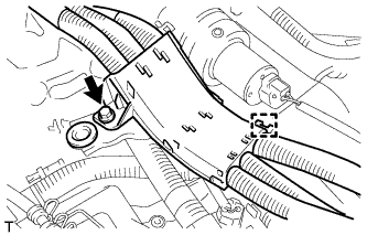
Remove the bolt and clamp shown in the illustration.
-
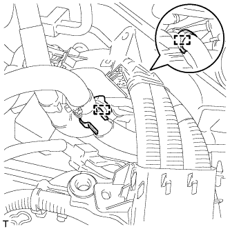
Disconnect the 2 water hose clamps shown in the illustration.
-
Disconnect the 2 clamps shown in the illustration.
-
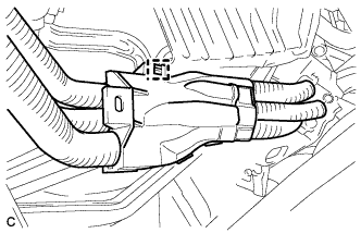
Disconnect the clamp shown in the illustration.
-
w/ Active Stabilizer System:
-
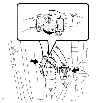
Disconnect the 2 connectors as shown in the illustration.
-

Disconnect the 2 clamps.
-
Remove the 2 nuts and wire harness bracket.
-
-
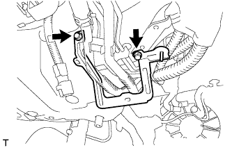
Remove the 2 bolts and wire harness bracket.
-
Separate the nut and heater pipe.
-
Remove the 2 nuts and water hose bracket.
-
Remove the 2 nuts and bolt shown in the illustration and remove the No. 3 wire frame from the cabin.
-
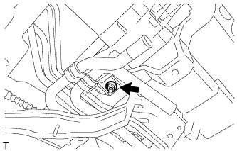
Remove the nut shown in the illustration. (for AWD)
-
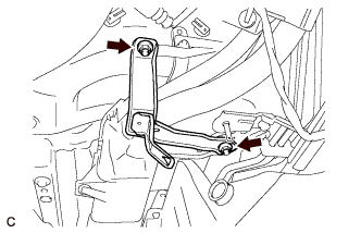
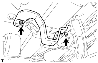
Remove the 3 nuts shown in the illustration.
-
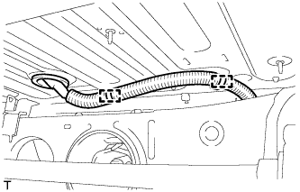
Remove the 2 clamps as shown in the illustration and remove the No. 3 wire frame from the cabin.
-
w/ Active Stabilizer System:
-
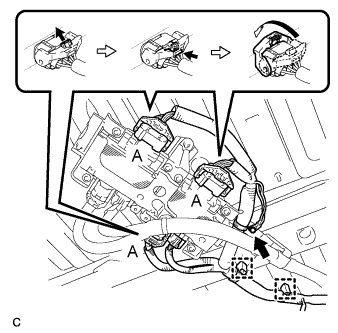
Disconnect the 3 connectors (A) as shown in the illustration.
-
Disconnect the connector and 2 clamps.
-
Remove the bolt.
-
-
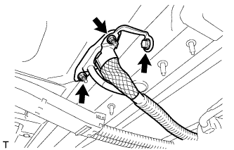
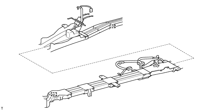
Disconnect the 3 clamps shown in the following illustration and remove the No. 3 wire frame.
-