MOTOR GENERATOR CONTROL COMPUTER INSTALLATION

Note
Do not cross-thread the screws when installing them.
-
HOW TO PREVENT STATIC ELECTRICITY
Note
-
Static electricity should be eliminated when removing/installing the inverter with converter assembly.
-
Do not touch the electronic components of a circuit board.
-
Keep clothes away from electronic components.
-
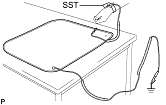
Place parts removed from the inverter with converter assembly on SST (anti-static mat).
-
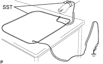
Wear SST (wrist band).
- SST
- 09890-47010
-
Connect the ground clip of the SST (anti-static mat) securely to a ground point provided in the workshop or on a workbench (anchor bolt).
- SST
- 09890-47010
Tech Tips
If the ground clip cable is too short, use an extension cable.
-
Connect the ground clip of the antistatic wrist strap securely to the specified point of the antistatic mat.
-
After removing the converter cover, perform work with bare hands to prevent damage from static electricity and entry of foreign matter.
-
-
INSTALL MOTOR GENERATOR CONTROL COMPUTER
Note
-
Do not touch the electronic components of the circuit board.
-
Do not allow any foreign matter or water drops to enter the inverter with converter assembly.
-
for 2WD:
-
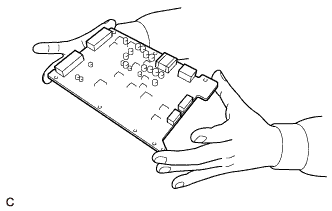
Hold the corners of the motor generator control computer and install it to the inverter with converter assembly.
-
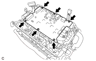
Install 6 new screws.
- Torque:
- 1.9 N*m { 19 kgf*cm, 17 in.*lbf }
-
Connect the 6 motor generator control computer connectors.
-
-
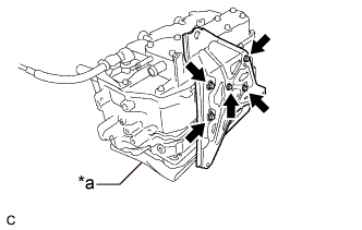
for AWD:
-
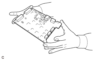
Hold the corners of the motor generator control computer and install it to the inverter with converter assembly.
-
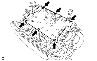
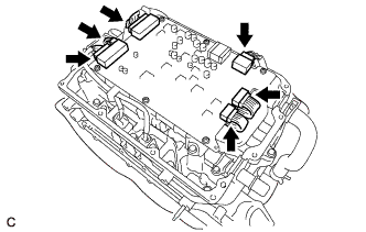
Install 6 new screws.
- Torque:
- 1.9 N*m { 19 kgf*cm, 17 in.*lbf }
-
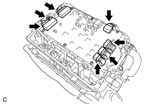
Connect the 7 motor generator control computer connectors.
-
-
Make sure that the motor generator control computer is free of foreign matter.
-
-
INSTALL CONVERTER COVER
Note
-
Do not touch the electronic components of the circuit board.
-
Do not allow any foreign matter or water to enter the inverter with converter assembly.
-
Do not touch or allow foreign matter, such as grease, to adhere to the contact surfaces of the converter cover and inverter with converter assembly.
-
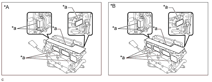
Apply seal packing (diameter: 2.0 to 4.0 mm (0.0787 to 0.157 in.)) in a continuous line to the locations shown in the illustration.
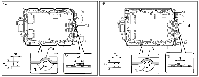
Text in Illustration *A for 2WD *B for AWD *a Seal Packing *b Bolt Hole *c 2.0 to 4.0 mm (0.0787 to 0.157 in.) *d Starting Position for Seal Packing Application *e Overlapping Area of Seal Packing (Side View) *f Below 10 mm (0.394 in.) Seal Packing Toyota Genuine Seal Packing 1282B, Three Bond 1282B or equivalent Note
-
Start applying seal packing from the area (*d) shown in the illustration.
-
Install the converter cover within 3 minutes of applying seal packing.
-
Tighten the bolts within 15 minutes of applying seal packing.
-
-
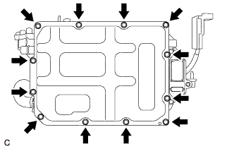
Install a new converter cover to the inverter with converter assembly with 12 new bolts.
- Torque:
- 4.2 N*m { 43 kgf*cm, 37 in.*lbf }
-
Remove SST (wrist band).
-
-
INSTALL NO. 1 INVERTER BRACKET
-
Text in Illustration *a Cloth Set the inverter with converter assembly on a clean cloth, etc. and orient it as shown in the illustration.
-
Install the No. 1 inverter bracket to the inverter with converter assembly with the 5 bolts.
- Torque:
- 10 N*m { 102 kgf*cm, 7 ft.*lbf }
-
-
INSTALL WIRE HARNESS CLAMP BRACKET
-
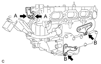
Install the 3 wire harness clamp brackets to the inverter with converter assembly with the 4 bolts.
- Torque:
- Bolt (A)
- 8.0 N*m { 82 kgf*cm, 71 in.*lbf }
- Bolt (B)
- 8.5 N*m { 87 kgf*cm, 75 in.*lbf }
-
-
INSTALL INVERTER TERMINAL COVER
-
Set the inverter with converter assembly and orient it as shown in the illustration.
Text in Illustration *A for 2WD *B for AWD *a Protective Tape - - -
Remove the protective tape.
Note
Do not allow any foreign matter or water to enter the inverter with converter assembly.
-
Install the inverter terminal cover Click here.
-
-
INSTALL INVERTER WITH CONVERTER ASSEMBLY
-
OPERATION CHECK
Tech Tips
After the repair, check the operation as follows. Then check for DTCs again.
-
Operation check 1
-
Connect the intelligent tester to the DLC3.
-
Turn the power switch on (IG) and clear the DTCs according to the prompts on the intelligent tester screen.
-
Turn the power switch on (READY).
-
Warm up the engine with park (P) selected and the A/C turned off until the engine stops.
Tech Tips
The engine will stop automatically when it is warmed up.
-
Depress the accelerator pedal with park (P) selected to start the engine.
-
As soon as the engine starts, release the accelerator pedal and wait until the engine stops.
-
Select drive (D). Creep the vehicle forward 5 m (16.4 ft.) with the engine stopped and without depressing the accelerator pedal.
Note
Confirm the safety of the surrounding area before moving the vehicle.
-
Select reverse (R). Creep the vehicle backward 5 m (16.4 ft.) with the engine stopped and without depressing the accelerator pedal.
Note
Confirm the safety of the surrounding area before moving the vehicle.
-
-
Operation check 2
Tech Tips
The current at the AMD terminal cannot be measured directly because of space limitations. Measure the current flowing at the auxiliary battery instead.
-
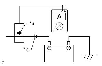
Text in Illustration *a Probe Direction *b Current Flowing to Auxiliary Battery Connect the AC/DC 400 A probe of the tester to the positive auxiliary battery line.
-
Turn the power switch on (READY) and leave the vehicle as it is until the electric current flowing to the auxiliary battery becomes 10 A or less.
-
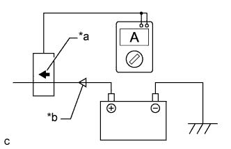
Text in Illustration *a Probe Direction *b Current Flowing from Auxiliary Battery Change the orientation of the AC/DC 400 A probe.
-
Measure the current flowing from the auxiliary battery with the power switch on (READY), the headlight position switch and blower motor switch in the HI position, and the rear window defogger turned on.
Standard Current Item Condition Specified Condition Current flowing from auxiliary battery Power switch on (READY)
(The headlight position switch and blower motor switch are in the HI position, and the rear window defogger is turned on.)
0 A or less
(No current from auxiliary battery)
-
Turn the power switch off.
-
-